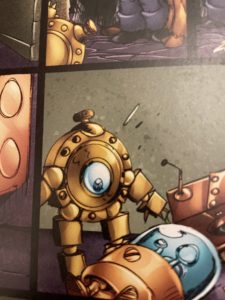
We decided to finally make an attempt to build a Dingbot robot based on the girl genius web comics.
Please note, this material is provided for informational purposes only and is not a guide on how to create the designs. Please take a look at our disclaimer.
Our design is based on the first BingBot, a small robot similar to a pocket watch. Below is a image of a GirlGeniusOnline Dingbat in action.
As the series continue she create a variety of different BingBots and even Wingbots.
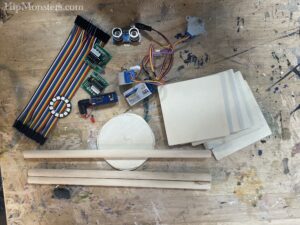
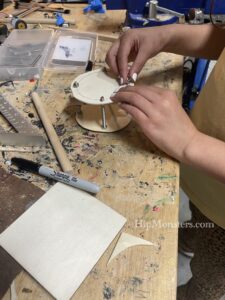
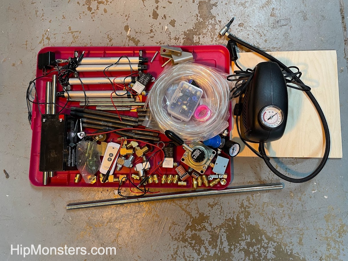
After we have settled on a design on paper we like laying out all the components on our workbench and start visualizing how the pieces fit together and to make sure we have all the parts we need.
We made the design as small as possible but still fit all the electronics including a RaspberryPi Nano. We wanted the design to be a fully functioning computer. The idea was when it is not running about it can be used to play music or video games.
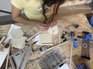
The front and back to the robot are plywood circles that will serve as bases for all the electronics. To make sure the two sides align, we clamped two pieces of plywood together and used coping saw. To smooth out any irregularities, clamped them together again and sanded them repeatedly.
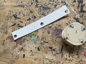
We used 2 inch bolts to separate the front and back plates. The is the smallest width that will still be able to hold all of our electronics. After repeated measuring, we drilled the holes while they were still clamped. This assured the bolts would align. Since the bolts are part of the atheistic of the robots it is important to get the positions correct.
We used three nuts and four washers per bolts to acts as spacers. To keep the bolts from loosing we used lock bolts (which can prove difficult to put on) and a pneumatic tubing in between the top and bottom bolts. We have used pneumatic tubing as spacers before in our robot designs and it works great even after years of use.
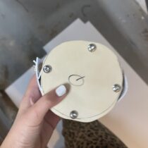
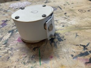
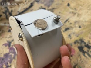
Once the two plates were secured we cut a strip of plastic to seal the gap. We thought using the side to access the components would be a unique and useful design. Normally, we prefer to have most of the electronics exposed but dingbot has a clean and elegant design. We recommend testing your layout of a sheet of paper first before cutting the holes in the plastic.
After a few trial and error we managed to secure the plastic strip. The first one broke so the second time we heated it with a blow dry to make it more flexible.
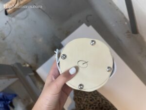
Down the center of the robots is a wooden dowel which will server as the spine for the robots. The legs and arms will both be anchor to the spine.
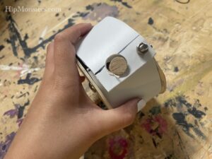
Here is a bottom view showing the spine.
We are not 100 percent happy with how the plastic strip pops out but we will try applying low heat again and try and mold it into shape.
Although you cannot see them, the design fits a RaspberryPi Nano, two motors, h-bridges, tons of wiring and a battery neatly.
Next step is to design the legs! We are leaning towards a toy robot inspired design.
Inspired by the Boston Dynamics robot videos, steampunk art, and Girl Genius, the HipMonster team set out to make their robotic dog walk to take for a walk on our city street. This project ended up being a lot harder than we imaged and took two years to complete. This greatly impacted our work on the HipMonsters’ website which is just now being updated with new content. So, finally, we give you the making of Number Five!
Please note, this material is provided for entertainment and informational purposes only and is not a guide on how to create the designs. Please read our disclaimer.
Getting Started
Base supplies to get started:
Brass Pipe Fitting, 4-Way Tee, Female Pipe (1, 1/4″ x 1/4″ x 1/4″ x 1/4″ NPT)
Brass Pipe Fitting, 90 Degree Barstock Street Elbow, 1/4″ Male Pipe x 1/4″
Brass Pipe Fitting, Barstock Tee, 1/4″ x 1/4″ x 1/4″ NPT Female Pipe
Black Steel Pipes ,close nipple pipe, 1/4 in. x 8 in, Black, 5 Pack
Black Steel Pipes, close nipple pipe, 1/4 in. x 6 in, Black, 5 Pack
Black Steel Pipes, close nipple pipe, 1/4 in. x 2 in, Black, 5 Pack
Hex Nipple Coupling Set – 1/4-Inch NPT x 1/4-Inch NPT,Solid Brass, Female Pipe
3/8 Inch Stainless Steel Cable Clamp
90-degree Swivel 1/4-Inch Male NPT x 1/4-Inch Female NPT
Clear 6mm OD 4mm ID Polyurethane PU Air Hose Pipe Tube Kit 10 Meter 32.8ft
Pneumatic Rotary Lever Hand Valve 1/4” N PT Air Flow Control 3 Position 4 Way
Pneumatic 16mm Bore 150mm Stroke Air Cylinder Double Action
Bike Pump
Building on our experience creating Number Three, we used piping to build the skeleton for the robot. To make it stronger to withstand the force of walking we used 1/4-inch steel pipes and pneumatic pivot joints rather than PVC tubing. After that, we assembled the legs using the pivot joins to allow the legs to move.
Assembly begins!
After the legs were completed, we built a spine to help attach the legs and provide an attachment platform for the batteries, controller, and engine.
The skeleton is coming together
When Number Three moved, the legs would frequently come loose so we made sure to be attached tightly to the spine. We knew from other robots we built that the vibrations of a running robot tended to unscrew bolts and screws. So, getting everything put together as tight as possible is essential.
Final tightening of the frame
The spine takes a little patience to screw together because we used three parallel sets of pipes for strength. It proved difficult to screw them in at the same time and the best approach was to take it slow and calmly.
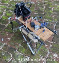
Side view of the completed skeleton
This is the side view of Number Five with most of the pneumatic pistons in place. We had two powering the back legs and four to power the front legs which did most of the pulling. We found from the full-scale test pull was better than push for control. If a front leg got stuck and the back legs still pushed forward the robot would veer to the left or right.
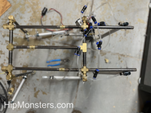
Below is a top view. The front part of the skeleton does not have a spine. This was originally to enable us to adjust the strides of the legs but that ended up being too finicky and we instead locked them in place. Sadly, we don’t have a clean attachment point for a head if we ever want to add one.
Top view of the skeleton
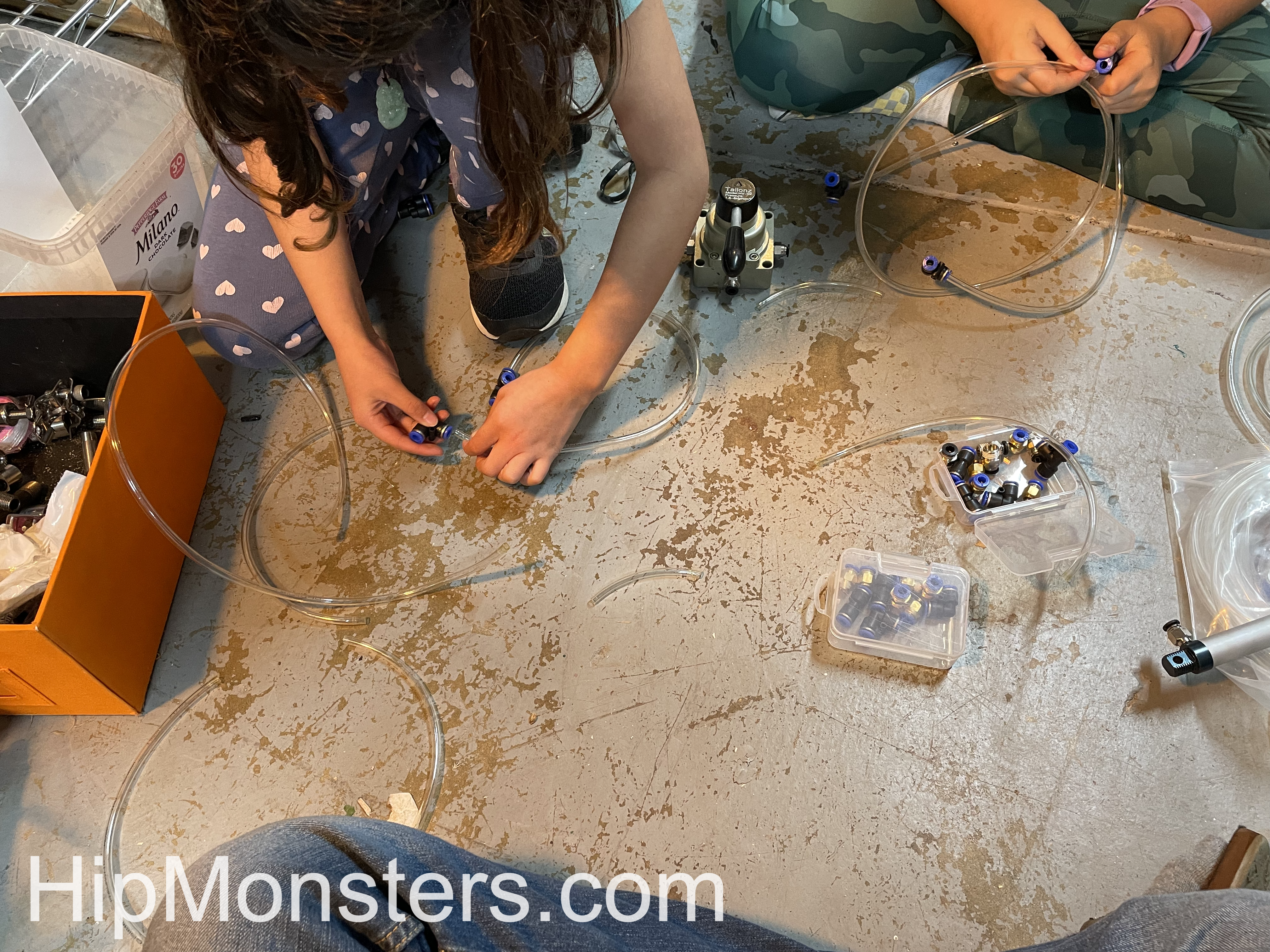
Next, we started connecting the air tubes to the pistons. We first laid out how the piston would attach to the frame then cut the tubes to link them to the engine. We made sure that they were long enough not to get yanked out, but short enough not to get caught in the robot’s legs.
Fitting the pneumatic tubes
The tubing took a few attempts to get the length right. It is better to be too long than too short, so we have a bag filled with little bits of extra tubing. The tubing connects the piston to the engine. In the beginning, the engine was a bike pump powered by a kid but the final version would have a car air pump.
While attaching the pipes we recommend color coding the pipes with a little bit of nail polish or colored tape. You want the legs to be connected oppositely. If a right piston is rigged to push when the air is redirected, you want its mirror to pull.
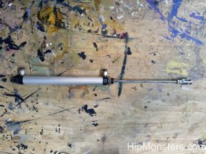
Each piston has two connections:
one at the top which makes the rod push out,
one in the middle pulls the rod back.
Close-up of an Air Piston
Below is a gif of two pistons connected in opposition. This will enable the robot to walk with a stride.
Testing the pistons
Below is the first full-scale test. We used a bike pump to better control power. The bike pump worked remarkably well for most of our small-scale tests and was significantly quieter than the air pump. Plus it is cool to power a robot with a bike pump. As you can see… this test failed hilariously.
Test number one
The first test showed that controlling double-jointed legs was very difficult so we decided to shorten the legs as well as do tons of additional modifications. With lots of tubing, it tangles easily and it is hard to figure out where the problem is. We also added knees to stop the legs from overextending and falling.
After tons of modifications
The second full-scale test was much more successful and operated as we expected. This floor has a slight downward tilt but it also works in the opposite direction; admittedly a bit slower. It is still operated by a manual switch but the engine is now a car pump.
Test 2
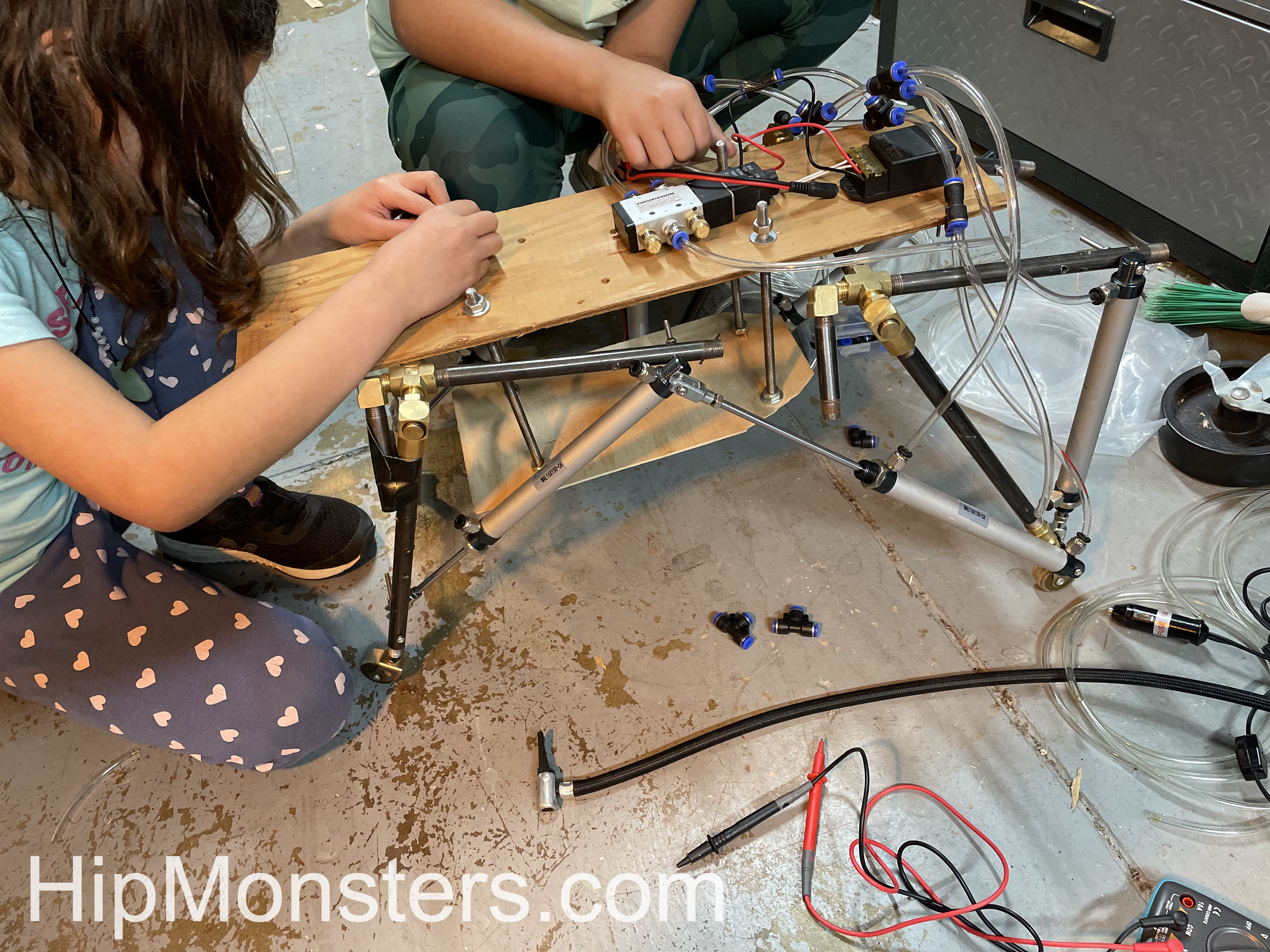
At this point, number five was powered externally and controlled with a manual switch. Our final goal was to be able to walk number five in our neighborhood on Halloween, so we added batteries, electronic air flow controls, and a remote control.
Adding control units
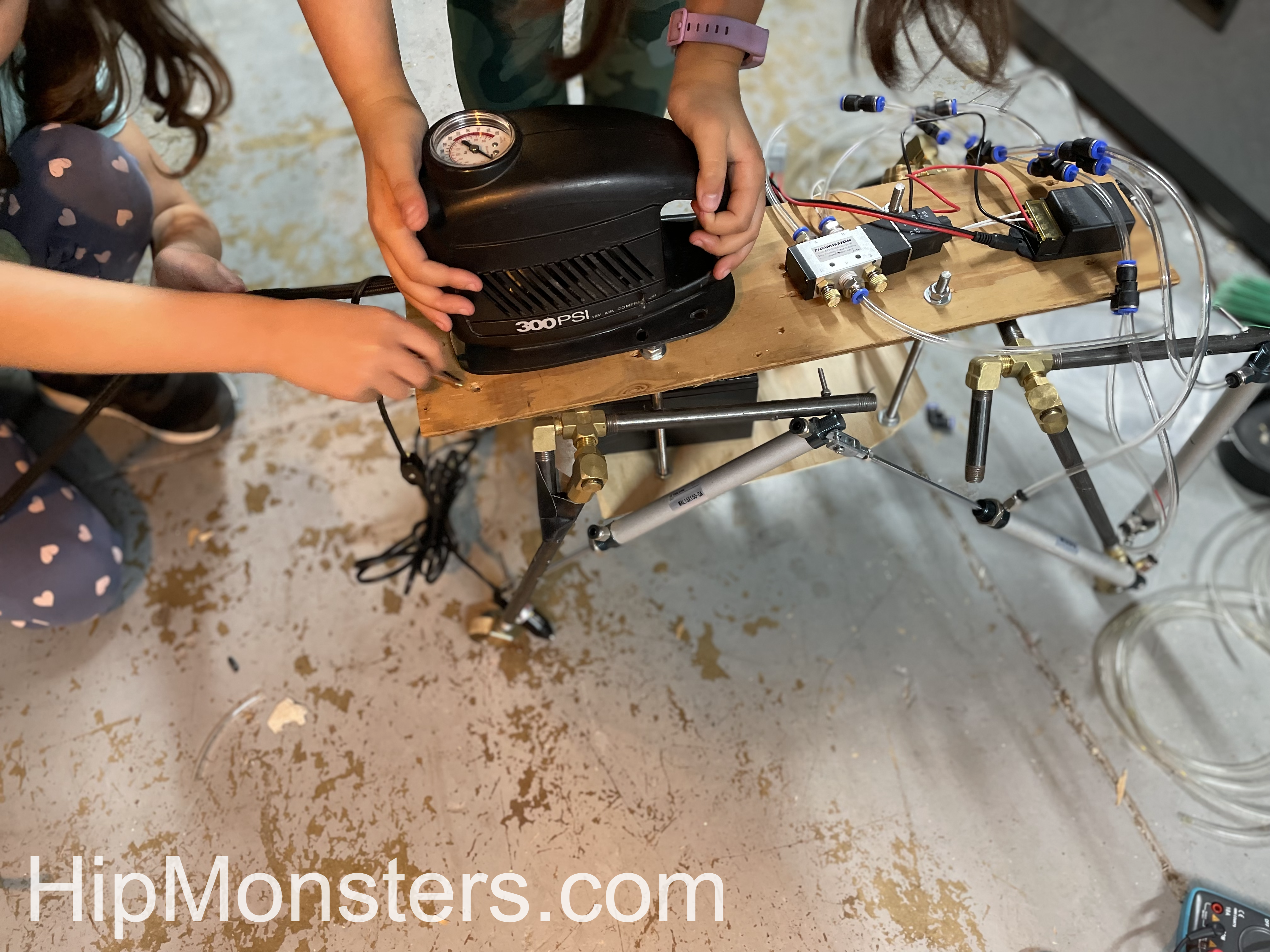
The engine was an old portable air compressor for car tires that was super light and used little power. To make Number Five portable, it needed to run on a 12-volt battery which meant all the electronics had to run off of 12 volts as well. Luckily 12 volts is the standard power supply so finding the right parts wasn’t too difficult.
Adding the engine
At this point Number Five was completely self-contained and controlled by a remote. We moved the battery to the center of Number Five to give it a lower center of gravity. When we first put it together the first time it was clear it would fall over easily if the battery was on top. So we quickly built a lower platform that rested between the leg. The pump was light enough to stay in the back clear from the movement of the front legs.
Here is the first test of the fully remote Number Five. We had more slippage than we had in the prior tests; the weight of the battery and air pump impacted the wheel traction more than we expected. So back to tinkering…
The key improvements this time were:
A rubber wedge in the wheels made them only spin in one direction
Shifting more weight forward.
Extended the forward stretch of the front legs giving a lurching motion forward that was very effective on flat or downhill surfaces.
Taking Number Five for a Walk
After the modifications were complete, the sister team was ready to take Number Five for a walk in our neighborhood! Number Five worked well on the rough city sidewalks and could even manage to walk up a slight incline as shown in this clip. Downhill Number Five went almost too fast. We have learned a ton and stay tuned for the next modifications!
For high res videos of Number Five in action check out our YouTube Channel!