Members of the 6165 MSET Cuttlefish, the Saratoga High School FIRST robotics team, noticed tons of pumpkins get tossed after Halloween only to end up rotting in landfills, where they release greenhouse gases even more harmful than carbon dioxide. Since composting isn’t yet widespread in their area, the Cuttlefish decided to take action.
For the past two years, they’ve hosted SMASH: STEM Madness at Saratoga High, a fun, hands-on event where they smash pumpkins in creative ways to promote composting and environmental awareness, while also sparking interest in STEM. Last year, over 200 attendees smashed over 650 pounds of pumpkins!
This year the Hip Monster’s team presented. We had a lot of fun, met some wonderful people, and were very impressed by the Cuttlefish team!
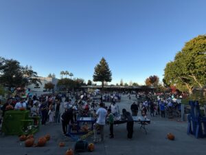
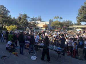
It was a perfect day for a festival and the Saratoga High School is beautiful with tall trees scattered throughout the campus.
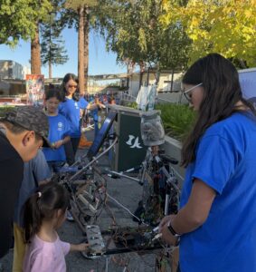
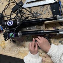
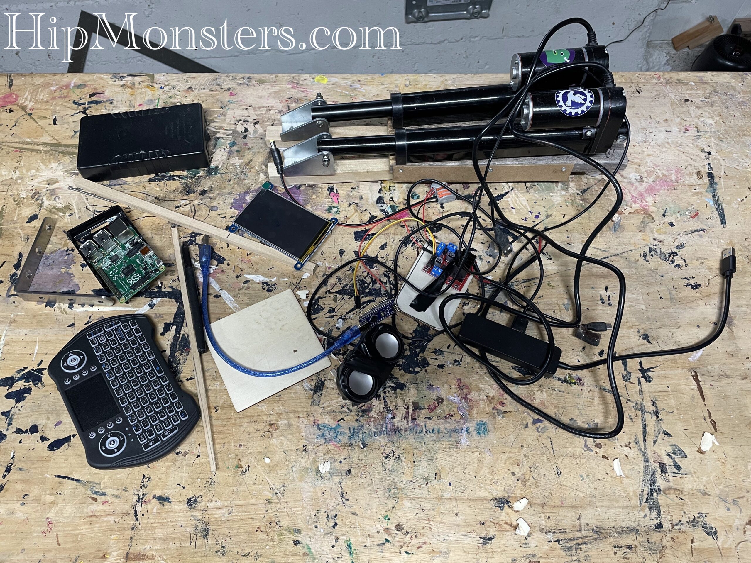
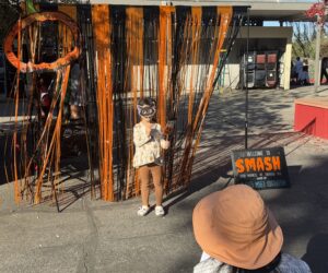
We brought Number Three and Number Eight. Here is a little girl using the touch sensor on Number Three.
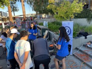
And here is some adults trying out Number Three.
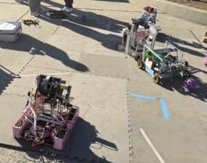
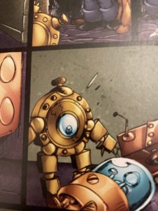
Here are the 6165 MSET Cuttlefish robots in action.
Kids loved having a second Halloween and several dressed up in their Halloween costumes.
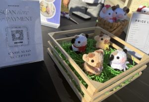
They had vendors and activities, to make this festival more interactive. There were also booths for organizations, like the public library and several clubs in the school.
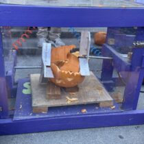
The main event, Pumpkin Smashing! People could pick out a pumpkin, weigh it, then wait for their pumpkin to be called for it to be smashed. You could also choose to carve the pumpkin. The person who chose the pumpkin gets to press the button themselves, making it a fun and interactive process.
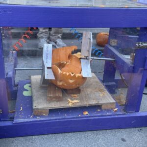
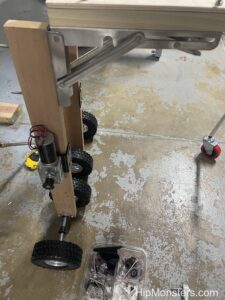
Here is a pumpkin being smashed. There were many different smashing machines for different sizes pumpkins. Our favorite was a hydraulic sledge hammer with 20 pounds of crushing force.
If you live in the Bay Area, make sure to attend next year.
Hope you find inspiration!