
2026 Updates
Here are some of our favorite spring flowers in our yard from this spring! These range from flowers we planted in the yard to wildflowers that appear every year.
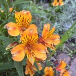


The orange flowers on the very left are orange Alstroemeria lilies, also called Peruvian lilies or Inca lilies. They are bulbs with long stocks and bright leaves that flower for a long time, from early spring to summer, and are one of our favorites. The ones in the middle are in the genus Myosotis, also known as woodland forget me nots, have clusters of small light blue flowers and fuzzy oval shaped leaves. They flower in spring and are self seeding. On the very right, we have Prunus serotina, commonly called black cherry. It has dark rubbery leaves and clusters of small white flowers. This is the first year that it flowered!
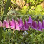
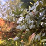

Here on the left we have Digitalis purpurea, also known as foxglove flowers, which flower from early spring to the start of summer. They have fuzzy green leaves and a cluster of bell shaped flowers on a long stalk. The flowers in the middle are Pieris japonica, also known as Japanese Andromeda, which flowers for a long time in spring. It has flowers resembling lilies of the valley, with old leaves that are tough and green, and new leaves that are soft and bright red. The final flower here is in the genus Rosa, known as roses, which flower in early spring, and sometimes multiple times a year. They have small bright flowers with dark green leaves and thick stems with thorns.


These spring flowers are all cineraria flowers, which flower late spring and summer. Their colors can range from bright pink to blue to purple, and often have flowers with multiple colors. They have large bright green leaves and have seeds that look like dandelions. We keep the dried stems up so the seeds can spread, so we will have many flowers every year.

This flowers is a type of lily, in the genus Lilium. They have large dark pink blossoms and thick petals.
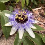


The first two flowers here are passion fruit flowers, in the Passiflora family which flowers all spring. The last one is Jasminum officinale, called white jasmine or pink jasmine. It flowers from late winter to spring and has very fragrant blossoms. These two are both vines and the passion fruit flowers grow especially well in the climate. This is also the first year that we had these flowers!
We live in San Francisco, so our weather is often foggy with occasional sunnier days or rain. Most of these flowers get part sun, and the temperature rarely gets over 80 degrees.
Hope you find inspiration!
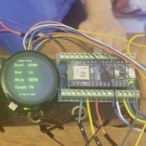
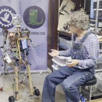
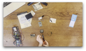
For better control and testing of our autonomous robots, we built wearable robot monitors to enable us to easily see what the robots were thinking and control the robots’ behavior wherever we are.
Please note, this material is provided for informational purposes only and is not a guide on how to create the designs. Please take a look at our disclaimer.
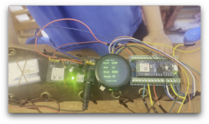
We designed the device around an Arduino Nano ESP32 and a 2-inch circular touchscreen display. The Aduino Nano ESP32 has built in Blue-Tooth (BLE) which enable it to communicate with our robots. It also has built in WiFi which will allow us to expand features in the future.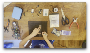
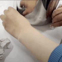
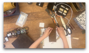
Sticking with our theme, we made a steampunk leather arm band to attach the device. Leather is ideal for quick DIY wearables because it is an insulator and tough to ignite. Flammable or conductive materials are not recommended.
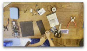
We used 1/4-inch-thick leather so it would better mold to a user’s arm. To attach to the arm, we used leather laces that can be easily adjusted to different-sizes.
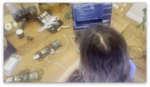
We loaded the software using the Arduino IDE. The Arduino IDE is free and can work with most of the popular microcontrollers. There are many online videos about how to use the Arduino IDE. The code was merged from two examples provided by the drivers for the LED screen and Arduino BLE.
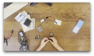
Next, we lay out the component and mark the attachment holes. Make sure to position the Arduino so the USB is accessible.
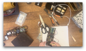
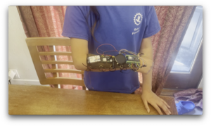
The wearable robot monitor is complete! The design is just right for a kid or and adult.The laces make it easy to adjust to any sized arm.
 Now we can keep track of our robots as they explore the world!
The robots use a Python script to poll for BLE devices. If the device is registered, the robot sends data about it sensor and reasoning, then checks for any commands. Since multiple people work with one robot, we do not pair the robot with one device but rather scan for all registered devices. The Python code is on our GitHub: HERE.
The Arduino code updates data when a server connects and sends any commands stored. The Arduino code on our GitHub: HERE
View the complete video on YouTube 
Happy Creating!
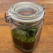
Mesocosms are controlled environments that simulate nature in an enclosed space. They are often used for experiments, but they are also a fun and convenient way to grow plants, because they are completely self-sustaining. In this article, we will teach you how to make a small DIY mesocosm.
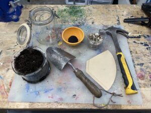
Materials:
Tools:
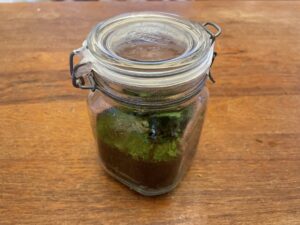
Step 1: Put a layer of pebbles about an inch thick at the bottom of the mason jar. This is for water drainage to make sure that the plants don’t drown
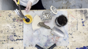
Step 2: Crush up some charcoal with the hammer until it is mostly a powder with some small pieces. The charcoal should just be enough to have a thin coating on top of the rocks. This will absorb moisture and prevent mold from growing.
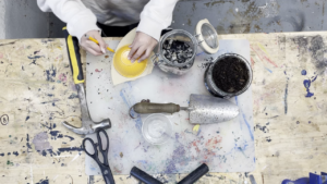
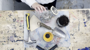
Step 3: Make a barrier between these layers and the next ones using either an organic coffee filter or sphagnum moss. We used a coffee filter because we did not have any sphagnum moss, but if you have both, we recommend using the moss. If using the coffee filter, use the scissors to cut a circle out of it that fits perfectly in the jar. If using sphagnum moss, make a thin layer that completely covers the charcoal.
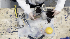
Step 4: Divide the remaining space in half and fill half of it with damp soil. If your soil is too dry, add water. This layer should be very thick but there should still be room for air on top and for the plants to grow taller. Don’t worry about having insects in the soil, they will not negatively effect the mesocosm, and are also self-sustaining.
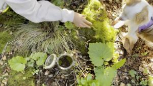
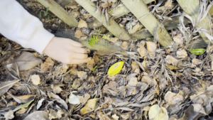
Step 5: Find some plants and moss. Make sure that your plants are not too big, because they will continue growing inside the mesocosm. We recommend using plants like ferns and moss that love high humidity environments, but you can use any. Once you are done, use a mister to spray it with water, or carefully water it. The goal is for the mesocosm to be sealed forever, so make sure you water it enough.
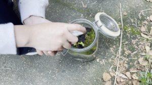
Step 6: If not using Parafilm, skip this step. Cut the Parafilm into strips almost an inch thick. Then peel off the backing and carefully stretch it as far as it can go without breaking. Stretch it around the rim of the jar and use several strips to make sure it is fully sealed. It might take a few tries to get this right.
Step 7: leave the mesocosm in a place with sunlight. The plants need sunlight to grow, and the heat will help make the mesocosm’s own water cycle.
If the mesocosm has any problems, like it doesn’t have enough water, or starts growing mold, you can unseal it to fix the issue before resealing it.
Congratulations, you have completed you DIY mesocosm!

Happy creating!
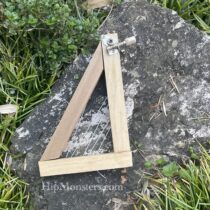
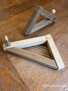
Here is a very old project that we had a lot of fun on but forgot to post about. This is our wooden harp, made in 2019, that we made after our ukuleles. This project was very simple, but never worked correctly. Here is a description of the harp and some changes we would make if we were to do this same project today.
Please note, this material is provided for informational purposes only and is not a guide on how to create the designs. Please read our disclaimer.
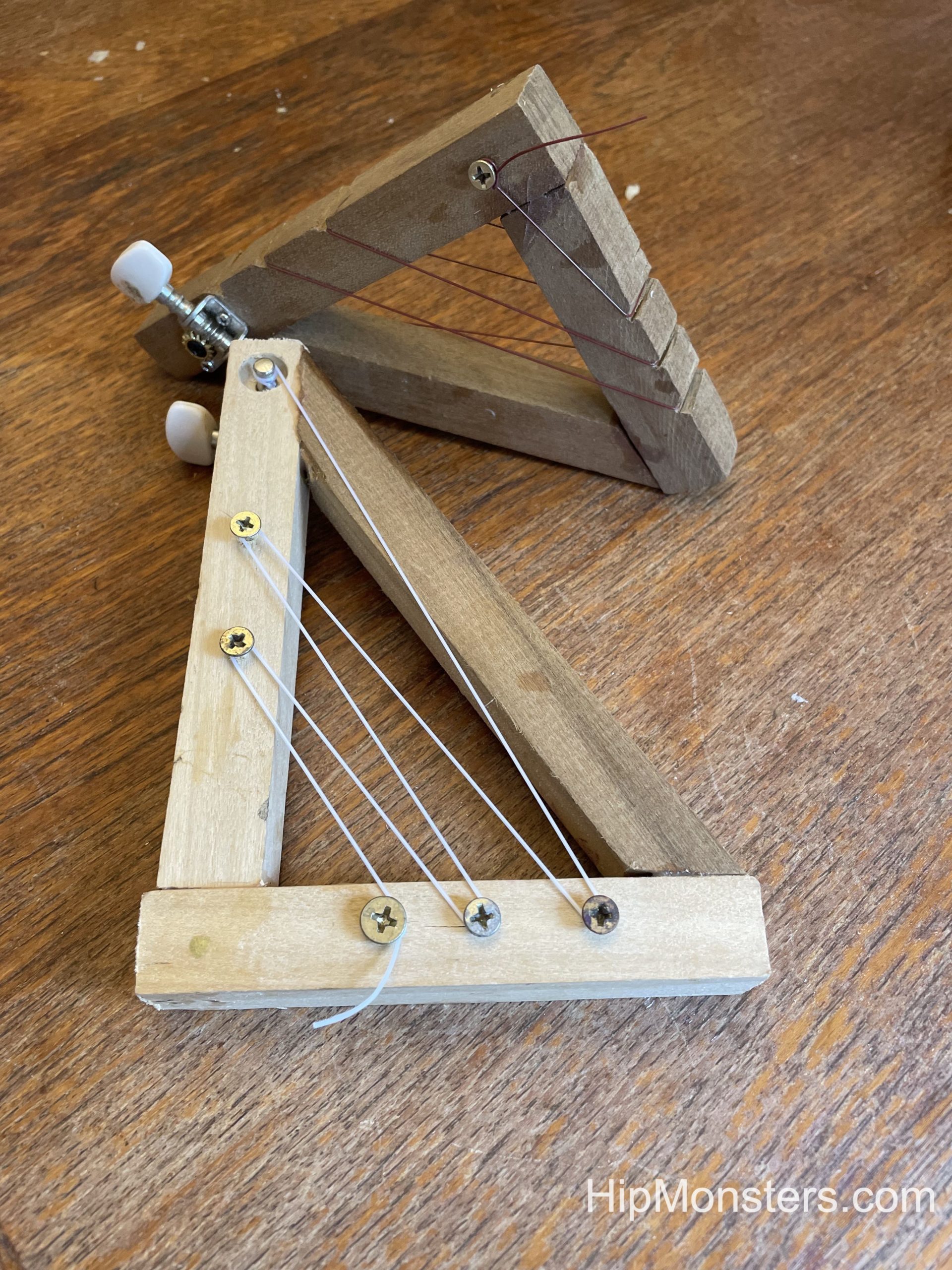
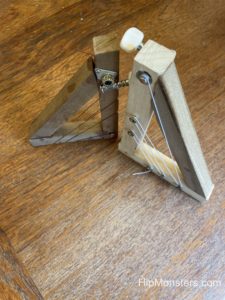
The harp has a classic triangular design, with one guitar tuner and one long string. The string is attached to the frame using screws. The whole thing is very small and light, you can hold it in one hand. A main problem was that there was not a big difference between the different notes on the harp. It was also hard to play the strings one by one because they were too cramped.
If the HipMonsters team were to make this project again, we would add more than one guitar tuner so you would have different sounds. After looking at pictures of smaller harps online, we noticed that many do not have the classic triangular design, but instead a more rectangular or ovular shape. By using that shape instead of the triangular one, the strings would be less cramped. The thick frame of the wooden harp also makes it look more messy and unwieldy, so we would either use thinner wood or make the harp larger.
Looking back on old projects is a great way to see growth. This harp was very creative, and it was impressive at the time, but there are many ways we would improve this.
Happy Creating!
Members of the 6165 MSET Cuttlefish, the Saratoga High School FIRST robotics team, noticed tons of pumpkins get tossed after Halloween only to end up rotting in landfills, where they release greenhouse gases even more harmful than carbon dioxide. Since composting isn’t yet widespread in their area, the Cuttlefish decided to take action.
For the past two years, they’ve hosted SMASH: STEM Madness at Saratoga High, a fun, hands-on event where they smash pumpkins in creative ways to promote composting and environmental awareness, while also sparking interest in STEM. Last year, over 200 attendees smashed over 650 pounds of pumpkins!
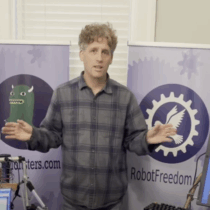
This year the Hip Monster’s team presented. We had a lot of fun, met some wonderful people, and were very impressed by the Cuttlefish team!
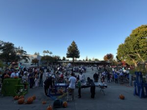
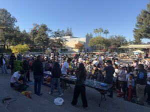
It was a perfect day for a festival and the Saratoga High School is beautiful with tall trees scattered throughout the campus.
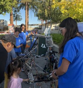
We brought Number Three and Number Eight. Here is a little girl using the touch sensor on Number Three.
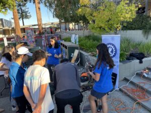
And here is some adults trying out Number Three.
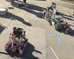
Here are the 6165 MSET Cuttlefish robots in action.
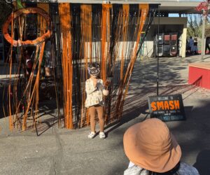
Kids loved having a second Halloween and several dressed up in their Halloween costumes.
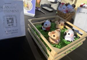
They had vendors and activities, to make this festival more interactive. There were also booths for organizations, like the public library and several clubs in the school.
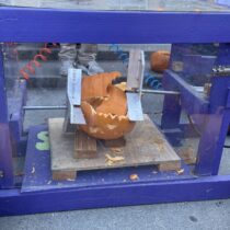
The main event, Pumpkin Smashing! People could pick out a pumpkin, weigh it, then wait for their pumpkin to be called for it to be smashed. You could also choose to carve the pumpkin. The person who chose the pumpkin gets to press the button themselves, making it a fun and interactive process.
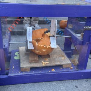
Here is a pumpkin being smashed. There were many different smashing machines for different sizes pumpkins. Our favorite was a hydraulic sledge hammer with 20 pounds of crushing force.
If you live in the Bay Area, make sure to attend next year.
Hope you find inspiration!
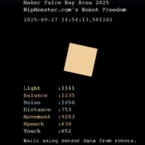
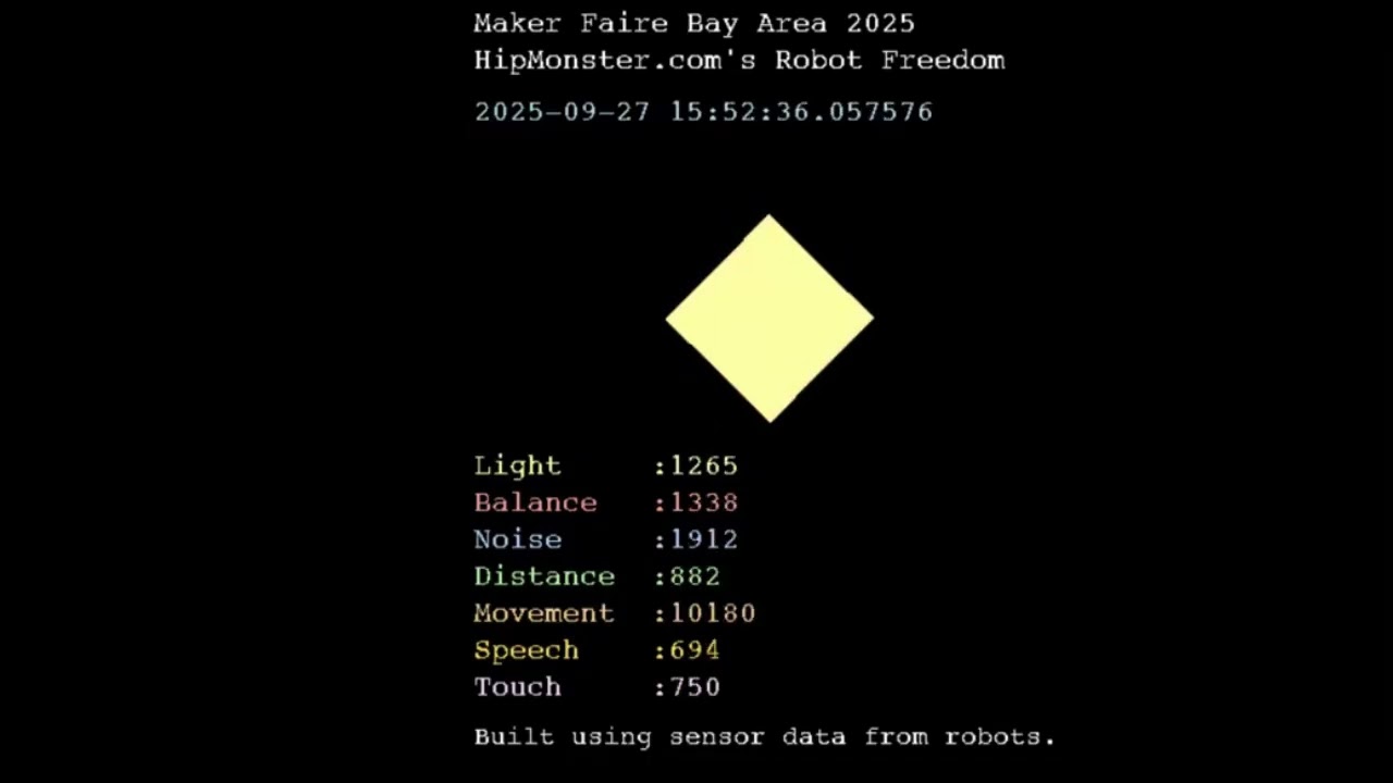
The Hip Monsters team had another wonderful time at this years’ Bay Area Maker Faire and our robots did too. Since we engaged the touch sensor at the end of each demo, we calculated we conducted at least 1239 complete demos over 3 days, three times what we achieved last year! Maker Faires are an ideal way to reach a tech savvy and engaged audience.
Check out the video below, generated based on the stimuli, emotions, and actions of Hip Monsters’ robot over the course of three days at the Maker Faire. Turn up the volume! The sounds are based on the robot’s simulated emotional response to the stimuli.
The robots recorded the following sensory data:
Noise: A sudden, loud noise. Represented by the color blue.
Distance: Motion within 1 foot. Represented by the color green.
Speech: The spoken word “robotics”. Represented by the color gold.
Touch: Contact on the touch sensor. Represented by the color pink.
Movement: Motion within 6 feet. Represented by the color orange.
Balance: If the balance sensor was moved. Represented by the color red.
Light: If there was a sudden change in light. Represented by the color yellow.
Frequency of Stimuli: How often or rarely the robots received stimuli. Captured by the Movement of the cube.
Mood: Happy or overstimulated. Reflected in the choice of sound.
THANK YOU everyone for making an incredible experience for humans and robots alike!


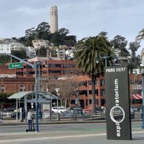
We went for a visit to the San Francisco Exploratorium in the Embarcadero pier 15. The Exploatorium teach science, technology, art and math (STEAM) like no place else on earth. Most of the exhibits are one of a kind creations straight from their prototyping workshop designed to engage audiences of all ages. The Exploratorium has over 600 exhibits that visitors can interact with.

Situated in the middle of San Francisco’s piers, it is a perfect walking destinations with lots of sights, food and more to explore!

If you are not up for a walk, there is also a MUNI stop right outside the entrance.

There is a lot to see, if you are only going once make sure to prioritize which exhibits you must see.

Learn about human perception by taking a drink from this unique drinking fountain that is shaped like a toilet.

This is a cloud chamber, a machine that allows you to see particles. The cloud chamber was invented by a physicist named Charles Thomson Rees Wilson in 1911. The cloud chamber is filled with the supersaturated vapor of water or vinegar.

You can even look inside the prototyping workshop where engineers can build prototypes for complicated designs.

This device counts when you turn the first gear using more and more advanced technology. It goes from the ones place counted by a spinning gear, all the way to a computer.

This is a model of the mars rover Perseverance. Its jobs is to look for evidence of ancient life on mars and pick up rock and dirt samples that will be brought to earth in the future. It was launched in 2020 and landed on Jezero Crater in 2021, which used to be a crater lake.

In the far back you can see artifical geysers that go off several times an hour. One of our favorite ways to relax is to take a seat and watch as the pressure slowly rises.

The liquid Litmus display shows how electricity and water relax to create basic (blue) and acidic (yellow) solutions. 
Ever dream you can visit Dune? See a desert world trapped under glass ever changing as winds rip across its surface.

Brave the cold and get a great View of San Francisco while eating lunch.

Learn how a heat pump work and burn off some energy in this exhibit. A lot of the exhibits require a bit of elbow grease to work the body as well as the mind.

This exhibit about DNA shows different models of human heads. Each head is modeled after the sane DNA, showing that DNA is not the only factor that decided people’s appearances.

And we finish our tour with vibrating rings showing how vibrational frequencies affect objects like steel rings.
We only showed you a few of the countless exhibits hidden in every corner of the San Francisco Exploratorium. If you plan a visit we strongly recommend staying all day.
Hope you find inspiration!