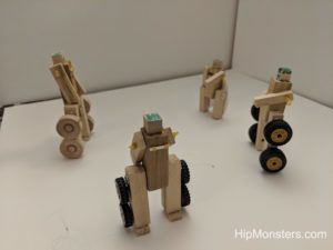
Middle School Robotics Presentation

The HipMonster.com’s team was invited to do a middle school robotics presentation last month to show kids the fun side of robotics and technology. The audience was so awesome and engaged making it a fun experience for everyone.

Steam punk slide on robots

The theme was how to take over the world using robots, making it fun to keep the students engaged. We used a steampunk template for our slides to match our robot designs and channeled Girl Genius when presenting.
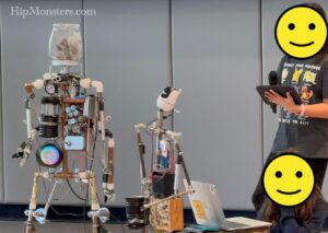
Steam punk robots in a presentation at school
Testing the controllers

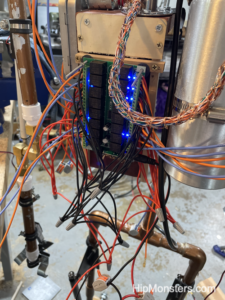
The robots got banged up a bit in transport but nothing completely broke. The biggest issue was the wires getting pulled out from the Arduinos. Luckily, it was only the breadboard jumper wires which are easy to put back in place. None of the soldered wires were broken which could have been very hard to fix. Breadboard jumpers are designed to be repeatedly taken on and off. They are like tiny USB cables and colored which helps see how what each cable is connected to (this is important because sometimes you can have dozens of wires). When you solder a wire to a controller      it can only be broken to be removed. You solder wires by using melted metal called solder and a really hot device to melt the metal. When a solder connection breaks you need to melt the metal again to reattach.
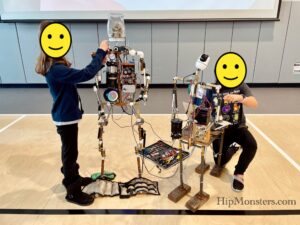
Two steam punk robots with two kids
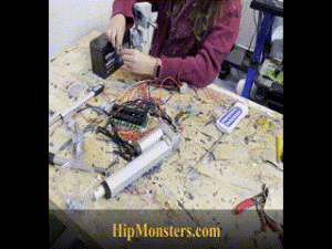
Fixing the wiring

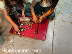
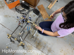
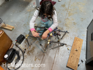
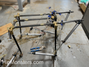
Here we are putting the finishing touches on Number Two and Number Three. All the robots traveled well and were up in running in thirty minutes except for one whose battery was faulty. When transporting batteries, we take extra care not to damage them and use a special carrying case.

We wrote a quick intro for the robots to perform to set the mood. After the intro, we dove right into robotics.
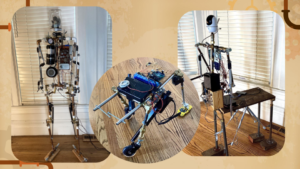
Three steam punk robots

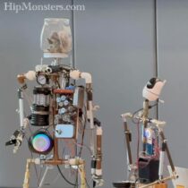
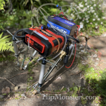
Here are three robot bodies. The first is Number Three. She can move his arms and hands, and talk. The middle is called Number Five. He can walk forward on his own using his four legs. The last is Number Two. He can’t do much, but he can still talk and move part of his arms.
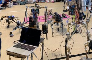
Four steam punk robots at a school
All the robots lined up in the gym

For each robot body, you need to do several things. There needs to be a skeleton, a power source, and something that makes the robot move. When we are thinking of designs for our robots we often think of animals that already exist. We also take inspiration from robots in different books and webcomics.
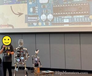
Robots at a school presentation
Presenting to the school

Number Four is the most complicated one. It took us over one year to build her, and she is still being modified. Many other robots were also not built all at once but were gradually assembled as we got new ideas.
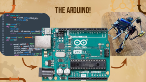
Arduino and a robot

After you build the body, you have to give the robot a brain. in our robots, we use something called an Arduino.

It is basically a tiny computer that you can program to do different things. For our robots, we use Arduino to make the robot walk on its own, so we don’t have to use a remote control. For one robot, the Arduino can also choose the direction that it walks in, and how fast it walks. You can find a simple example here.

We code the Arduino from our computer, then the Arduino sends messages to the robot to control it. We edit the code based on our observations and new ideas.
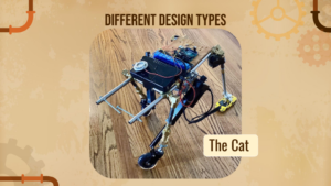
Steampunk cat robot

We have many different types of robots that can move their whole body, each type demonstrates a different way of moving. We have the 4-legged walkers, which are our first moving robot design. They are made of metal pipes and have four legs and wheels for feet. We put wheels on their feet because we wanted less resistance and friction, but we didn’t want the robots to just be like a remote-controlled car. We wanted them to walk. The design of the legs and the “knee” has made a big difference.
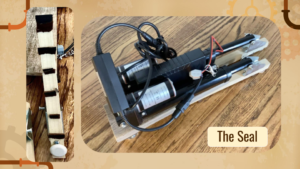
Robot seal

Another design is our Seal robot. This one is very different, as it only has two legs and no wheels. The legs pull themselves forward, powered by linear actuators. To make sure that the legs don’t just go backwards and stay in place, we put wedge-shaped bits of foam at the bottom of the seal’s legs. When the seal moves forward, the wedges give no resistance, but when the legs pull back, the wedges stop them.
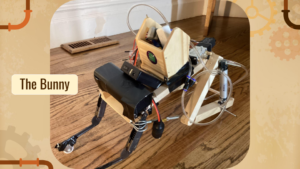
Steam punk Robot Bunny

The next robot is our Bunny robot. The bunny robot is also unique because it was originally designed to hop. The two back legs push it forward, thanks to the springs. This one is powered by air and pistons, so you can get the sudden jolt that is harder to achieve with linear actuators. This robot is also one of the only robots made mostly out of wood. We took the idea for the legs from our wooden toys.
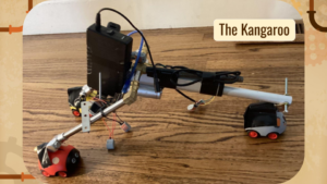
steampunk kangaroo robot

This is the Kangaroo. The kangaroo’s main difference besides the number of legs is the feet. The feet are small animal toys, designed to only go in one direction so they can move forward more efficiently. The back leg powers the whole robot, and we used linear actuators.
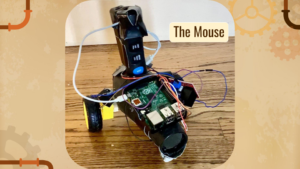
Steampunk mouse robot

The last robot is the Mouse. The mouse is just a broken blow-dryer attached to wheels from some old toys. It is very simple, so we decided to make it walk on its own, completely uncontrolled and completely randomly, controlled by the Arduino. You can see the code here.
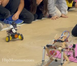
Robots
The mouse in action

Sorry, this photo was blurry, but the mouse was super fast that day-well charged batteries.

We want to give a big thanks to all who came to our presentation, and everyone who helped and supported us! this was our first big presentation, and we couldn’t be more happy with how it turned out!

Happy creating!

Number Three’s Controller

Please note, this material is provided for informational purposes only and is not a guide on how to create the designs. Please take a look at our disclaimer.

This post is an old one we forgot to publish a while back. Currently, Number Three is controlled by a script that is run on a Raspberry Pi sending commands to an Arduino. But originally Number Three was controlled by a wireless relay switch. We used wireless relays at first because they are simpler and we could just focus on the mechanics of the robots. As our robots got more complex, we had to migrate to Raspberry Pis. This post is a good overview of wiring a relay and even if outdated gives good insights. Also, a wireless relay may be useful in other situations.

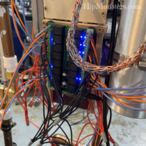
wiring for a robot control unit

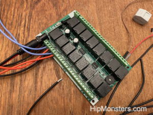
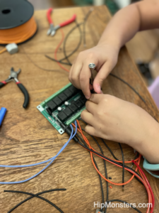
Here is a 12-volt, 16 relay wireless board. It is typically used for lighting but we have other purposes in mind- robots! To begin here are some basics. To control motor you change the power going it. A motor needs positive (red wires) and negative (black wires) energy to work. A relay controls power going to an engine. When wiring a relay the wire that gives the signal (what tells the relay to be on or off) is usually a color other than red or black. In this case the color is light blue.

wiring for a robot control unit

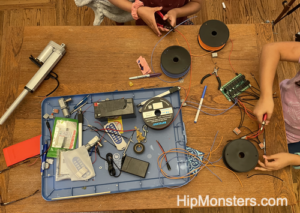
Honestly there is not too many parts to this build just the relay, linear actuators, wire nuts and a lot of wires. We recommend doing the build in an area easy to clean and free from pets. When you cut the wires little bits of wires can fall to the floor may end up in the foot o a pet.

wiring for a robot control unit

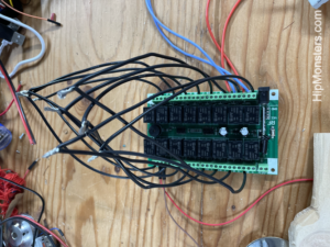
The wiring for the relays proved to be more difficult than we thought because the wires were slightly thinker than the connection wanted.  We had to twisted them tightly to fit them in. If you are buying wire go with a thin grade.

wiring for a robot control unit

When doing a wiring job of this scale, over 64 wires, it is best have a plan laid out before starting and if possible divide the labor. Our plan was to wire in order or wire type (signal, positive, negative, output).  To make it easy we cut all the wires the same length. To attach the wires we used wire nuts but have migrate to using lever connection nuts for quick builds.  The wire nuts proved to be too finicky and we don’t recommend them until the final build.

wiring for a robot control unit

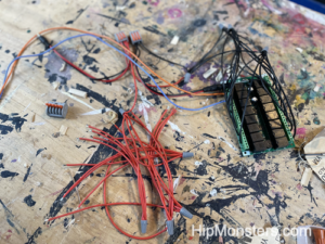
Here is a pile of pre-linked positive wires. Since we wanted to control a linear actuator we need to use two relays to control on the power. To make an actuator extend and retract you need to you flip positive to negative,  this is called reversing polarity. But one relay can on turn power on and off. So to be able to reverse polarity we needed to wire XOR logic gate. This is a good overview of how to control linear actuators and here is a good diagram on a XOR XOR logic gate.

wiring for a robot control unit

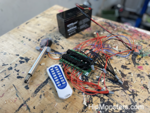
Here is the completed relay ready for testing.  Make sure all the wires are screwed in tightly and no fray wires are touching before pugging in the relay.

And what better way to test than knock something over and make a big mess!

wiring for a robot control unit

Here is the new controller installed on the back of Number Three. Since we are aiming for a steam punk robot the mass of wires is exactly the look we wanted.

Happy Creating!

Making of Number Six and Number Seven

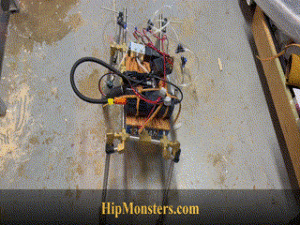
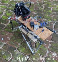
After finishing Number three, we wanted to make smaller and lighter walking robots. Leveraging what we had learned from building our first walking robot, we made two mini robots, Number Six and Number Seven!

Please note, this material is provided for informational purposes only and is not a guide on how to create the designs.  Please read our disclaimer.

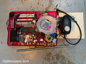
Because we had a completed robot design it was easy to make sure we had all the parts we needed before beginning. Since Number Six and Number Seven were smaller we were able to spend about the same amount of money but use lighter steal parts. We hoped the reduced weight would make for better walking performance.

making a robot

The steal tubes also had bolt threads as apposed to pipe threads. Pipe threads are “V” shaped which made it difficult to get a piece tightened pointing the correct direction. With bolt threads we could use a nuts to tighten the connection between the tube and the pivot joints however they were positioned.

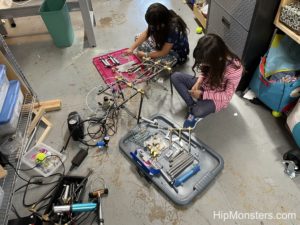
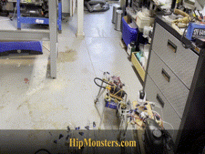
Working as a team the assembling went fast and in less than a day we had the beginnings of two robot. One trick we have learned is to use the floor as an assembling space. We are cramped for space and using step stools can be tricky in a workshop so the floor tends to be safer.

Here is a completed frame. It cannot stand yet and has to be held up. Here we had the initial knee designs. The knee design was important when we were developing the first walker. Later we switched to a tube in the piston rod that acted more like a spring to prevent the leg from over extending. What is critical in our approached is letting the robot fall forward but stop the fall before the robot is in a position it cannot recover from. The sister team learned this trick from a class at school where the teacher said when humans walk forward it is more like a controlled fall.

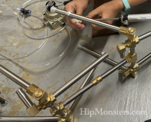
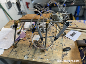
Now we start on installing the air pistons. We had to repeat this process many time because we kept switching around to position of the pistons and the direction of the air tube couplings. If the pistons are not the same on both side the robot will veer to one side and if the coupling are facing apposing ways the tubing becomes impossible to arrange.  We have found facing the coupling up is typically the best orientation.

We did have to modify the piston attachment by removing the peg. This did require a parent’s help as the clip that secured the peg was difficult to remove without breaking it.

making a robot

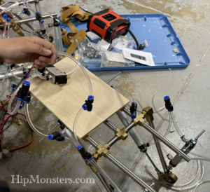
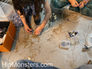
Next we began attaching the pneumatic air tubes. When measuring make sure to know were the pneumatic solenoid valve will be attached and account for the full movement of the legs. It is best to do one tube, test it, then do the opposites side. We found as we added tubes we had to change the initial lay of of the tubes. The tube work is a bit of an art form much like wiring a control unit.

Here is a close up of the all the piston installed.


making a robot

Here is another view of the tubing being fitted and a close up of the pneumatic solenoid valve. Make sure to do clean, straight cuts with a sharp scissors to assure not leakage when attaching to the couplings.

making a robot

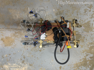
Here is a front view of a completed design for Number Six and Number Seven. For testing we used a leather book strap so we could reposition the components as needed. We also tested a number of different air pumps. This pump, which we did not use in the final design, was the quietest and used the least amount of power.  Latter, we switched to another model because this model kept shutting off after prolonged use.

DIY Robot

Like with other designed we used a garage door remote controller because it reverse polarity to the pneumatic solenoid valve which switches the air flow from one leg to the other enabling the robot to walk. It is the small black box in the center of the robot.

DIY Robot

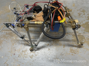
The battery we secure to the underside for protection (the light blue box under Number Six). Instead of doing lead acid battery for Number Six and Number seven, we switched to a 12V 6Ah Lithium Iron Phosphate Battery from our lead-acid battery due to it much lighter weight and increased amps.

DIY Steampunk walking robot Number 6Here is Number Six walking in our yard.

DIY Steampunk walking robot Number 7

Here is Number Seven walking in our workshop.

Steampunk DIY walking robots

And here we have all three robots, Number Five, Number Six, and Number Seven going for a walk together! The larger robot is Number Three. Number Seven is in front and Number Six is on the left.

Happy creating!
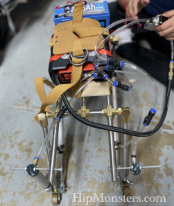
The Making of Number Five

Inspired by the Boston Dynamics robot videos, steampunk art, and Girl Genius, the HipMonster team set out to make their robotic dog walk to take for a walk on our city street. This project ended up being a lot harder than we imaged and took two years to complete. This greatly impacted our work on the HipMonsters’ website which is just now being updated with new content. So, finally, we give you the making of Number Five!

Please note, this material is provided for entertainment and informational purposes only and is not a guide on how to create the designs. Please read our disclaimer.

Getting started on a DIY robotic dog projects
Getting Started

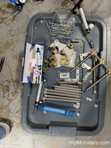
Base supplies to get started:

  • Brass Pipe Fitting, 4-Way Tee, Female Pipe (1, 1/4″ x 1/4″ x 1/4″ x 1/4″ NPT)
  • Brass Pipe Fitting, 90 Degree Barstock Street Elbow, 1/4″ Male Pipe x 1/4″
  • Brass Pipe Fitting, Barstock Tee, 1/4″ x 1/4″ x 1/4″ NPT Female Pipe
  • Black Steel Pipes ,close nipple pipe, 1/4 in. x 8 in, Black, 5 Pack
  • Black Steel Pipes, close nipple pipe, 1/4 in. x 6 in, Black, 5 Pack
  • Black Steel Pipes, close nipple pipe, 1/4 in. x 2 in, Black, 5 Pack
  • Hex Nipple Coupling Set – 1/4-Inch NPT x 1/4-Inch NPT,Solid Brass, Female Pipe
  • 3/8 Inch Stainless Steel Cable Clamp
  • 90-degree Swivel 1/4-Inch Male NPT x 1/4-Inch Female NPT
  • Clear 6mm OD 4mm ID Polyurethane PU Air Hose Pipe Tube Kit 10 Meter 32.8ft
  • Pneumatic Rotary Lever Hand Valve 1/4” N PT Air Flow Control 3 Position 4 Way
  • Pneumatic 16mm Bore 150mm Stroke Air Cylinder Double Action 
  • Bike Pump

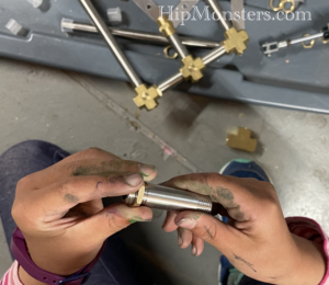
Building on our experience creating Number Three, we used piping to build the skeleton for the robot. To make it stronger to withstand the force of walking we used 1/4-inch steel pipes and pneumatic pivot joints rather than PVC tubing.  After that, we assembled the legs using the pivot joins to allow the legs to move. 

 Assembly begins on a DIY robotic dog project.
Assembly begins!

After the legs were completed, we built a spine to help attach the legs and provide an attachment platform for the batteries, controller, and engine.  

DYI robotic walker skeleton is coming together
The skeleton is coming together

When Number Three moved, the legs would frequently come loose so we made sure to be attached tightly to the spine. We knew from other robots we built that the vibrations of a running robot tended to unscrew bolts and screws. So, getting everything put together as tight as possible is essential.

Final tightening of the frame of the DIY walking robot dog
Final tightening of the frame

The spine takes a little patience to screw together because we used three parallel sets of pipes for strength. It proved difficult to screw them in at the same time and the best approach was to take it slow and calmly.

Side view of the completed DIY robotic dog skeleton
Side view of the completed skeleton

This is the side view of Number Five with most of the pneumatic pistons in place. We had two powering the back legs and four to power the front legs which did most of the pulling. We found from the full-scale test pull was better than push for control. If a front leg got stuck and the back legs still pushed forward the robot would veer to the left or right. 

Below is a top view. The front part of the skeleton does not have a spine.  This was originally to enable us to adjust the strides of the legs but that ended up being too finicky and we instead locked them in place.  Sadly, we don’t have a clean attachment point for a head if we ever want to add one.

Top view of the completed DIY robotic walker skeleton
Top view of the skeleton

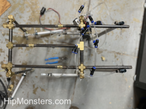
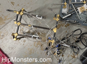
Next, we started connecting the air tubes to the pistons. We first laid out how the piston would attach to the frame then cut the tubes to link them to the engine. We made sure that they were long enough not to get yanked out, but short enough not to get caught in the robot’s legs.

 Fitting the pneumatic tubes to power the piston on the DYI robotics dog
Fitting the pneumatic tubes

The tubing took a few attempts to get the length right. It is better to be too long than too short, so we have a bag filled with little bits of extra tubing. The tubing connects the piston to the engine. In the beginning, the engine was a bike pump powered by a kid but the final version would have a car air pump.

While attaching the pipes we recommend color coding the pipes with a little bit of nail polish or colored tape. You want the legs to be connected oppositely. If a  right piston is rigged to push when the air is redirected, you want its mirror to pull.

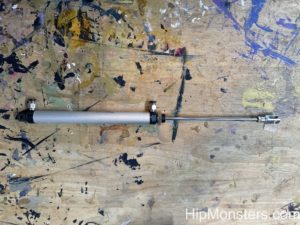
Each piston has two connections:

  • one at the top which makes the rod push out,
  • one in the middle pulls the rod back.
Air Piston
Close-up of an Air Piston

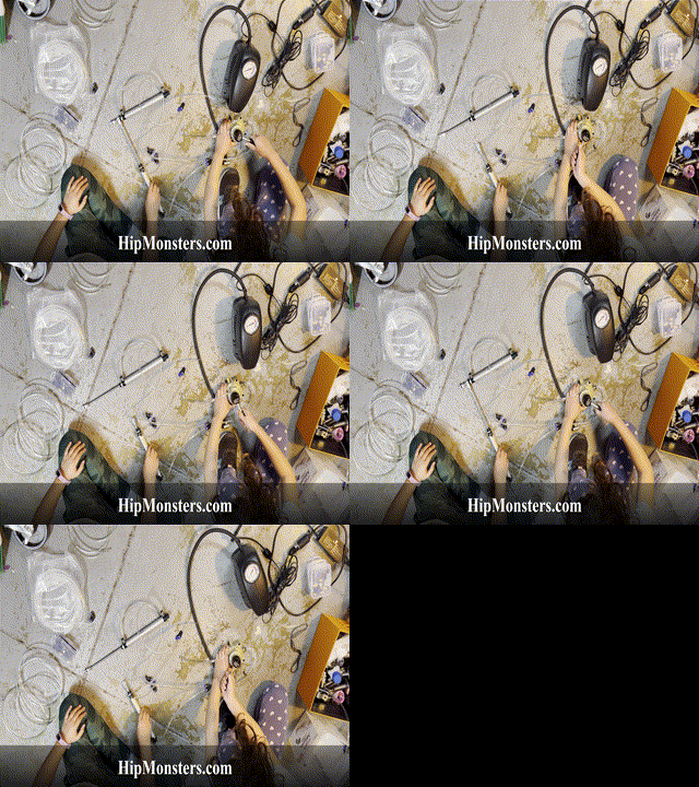
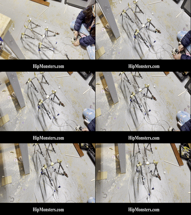
Below is a gif of two pistons connected in opposition. This will enable the robot to walk with a stride.

Testing the pistons on the DYI Robotic dog.
Testing the pistons

Below is the first full-scale test. We used a bike pump to better control power. The bike pump worked remarkably well for most of our small-scale tests and was significantly quieter than the air pump. Plus it is cool to power a robot with a bike pump. As you can see… this test failed hilariously. 

First test of the DYI robotic dog.
Test number one

The first test showed that controlling double-jointed legs was very difficult so we decided to shorten the legs as well as do tons of additional modifications. With lots of tubing, it tangles easily and it is hard to figure out where the problem is. We also added knees to stop the legs from overextending and falling.

Setting up the tubing on the DYI robotic dog
After tons of modifications

The second full-scale test was much more successful and operated as we expected. This floor has a slight downward tilt but it also works in the opposite direction; admittedly a bit slower. It is still operated by a manual switch but the engine is now a car pump.

Test number 2 of the DIY robotic dog
Test 2

At this point, number five was powered externally and controlled with a manual switch. Our final goal was to be able to walk number five in our neighborhood on Halloween, so we added batteries, electronic air flow controls, and a remote control.  

Adding wiring and remote control to DIY robotic dog
Adding control units

The engine was an old portable air compressor for car tires that was super light and used little power. To make Number Five portable, it needed to run on a 12-volt battery which meant all the electronics had to run off of 12 volts as well. Luckily 12 volts is the standard power supply so finding the right parts wasn’t too difficult.

Adding pump to DIY robotic dog
Adding the engine

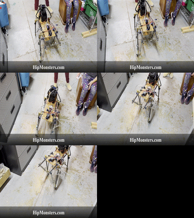
At this point Number Five was completely self-contained and controlled by a remote.  We moved the battery to the center of Number Five to give it a lower center of gravity. When we first put it together the first time it was clear it would fall over easily if the battery was on top.  So we quickly built a lower platform that rested between the leg. The pump was light enough to stay in the back clear from the movement of the front legs. 

DIY Robotic dog walking, Made by kids


Here is the first test of the fully remote Number Five. We had more slippage than we had in the prior tests; the weight of the battery and air pump impacted the wheel traction more than we expected.  So back to tinkering…

The key improvements this time were:

  • A rubber wedge in the wheels made them only spin in one direction
  • Shifting more weight forward. 
  • Extended the forward stretch of the front legs giving a lurching motion forward that was very effective on flat or downhill surfaces. 
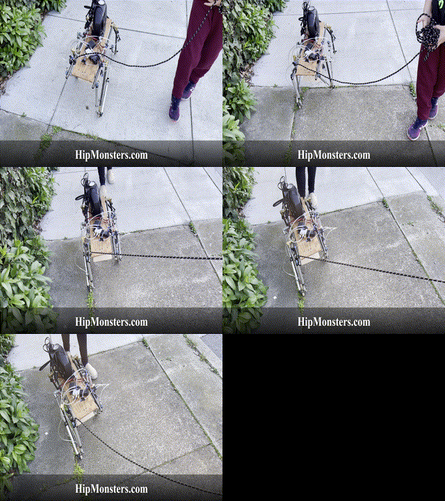
DIY Robotic dog walking on sidewalk
Taking Number Five for a Walk

After the modifications were complete, the sister team was ready to take Number Five for a walk in our neighborhood! Number Five worked well on the rough city sidewalks and could even manage to walk up a slight incline as shown in this clip. Downhill Number Five went almost too fast. We have learned a ton and stay tuned for the next modifications! 

For high res videos of Number Five in action check out our YouTube Channel!

Happy Creating!


The Making of Number Three

The Making of Number 3

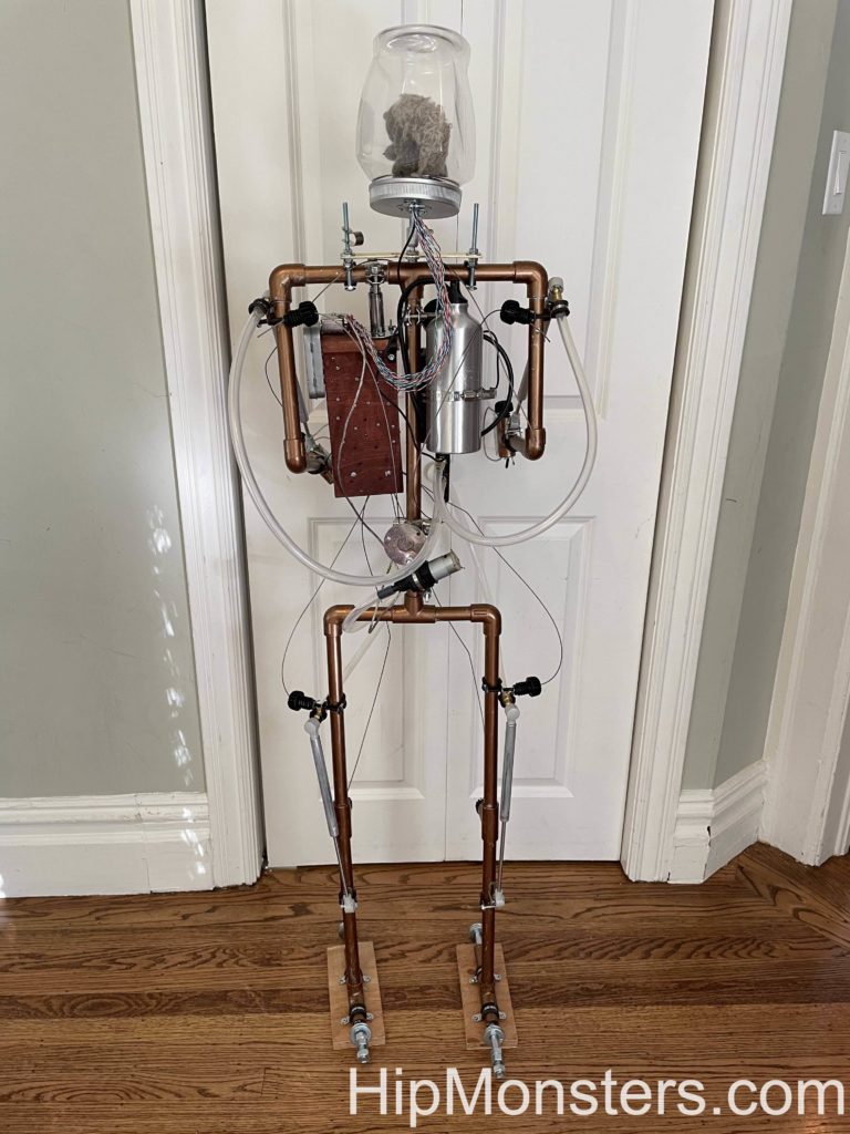
We saw the need for a new robot for halloween, so we made one. This is our steampunk squirrel powered robot Number 3. We wanted it to be as big as a kid to help with our Halloween decorations. Our other robots were small and not easy to see.  Our plan was for a big robot with lights and room to grow as we came up with new ideas.

Please note, this material is provided for informational purposes only and is not a guide on how to create the designs.  Please read our disclaimer.

Getting started on steampunk inspired robot
Getting started

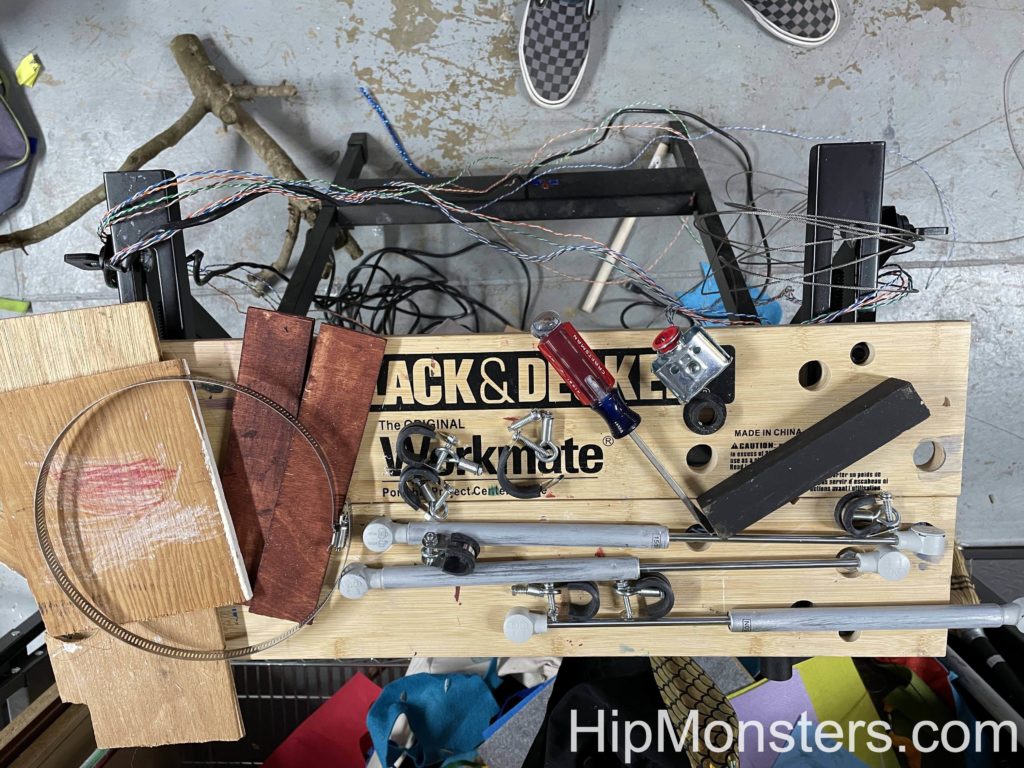
These are some of the parts that we used. We gathered most of it from unused parts from other projects. This project ended up being a great way to recycle old parts and scapes and it made it look even more steam-punky.
Odd and ends for the steampunk inspired robot
Scrape parts

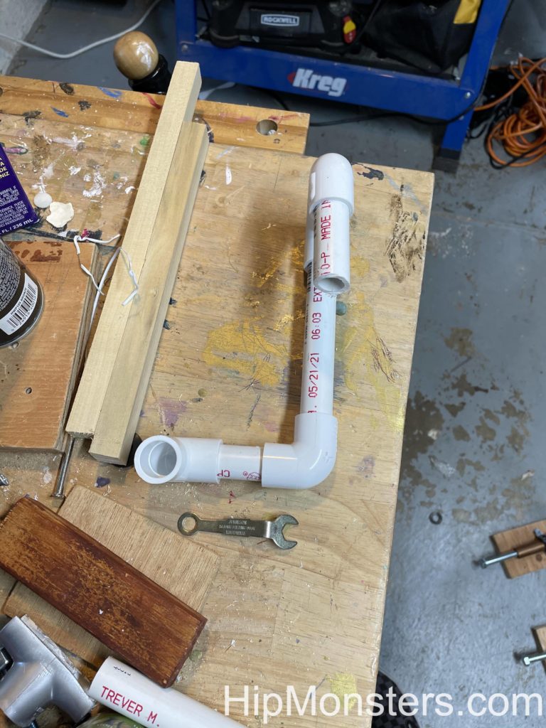
We used PVC pipes for the skeleton of our robot because its strong and lightweight. Also we had fitting from remodeling that would attach to the pipes and let us hangs details. The pipes are standard so if we did need to buy anything it would be easy.

Completed steampunk inspired robot
Completed Robot

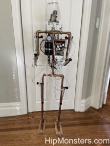
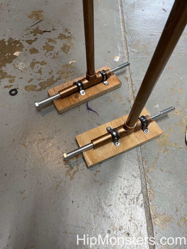
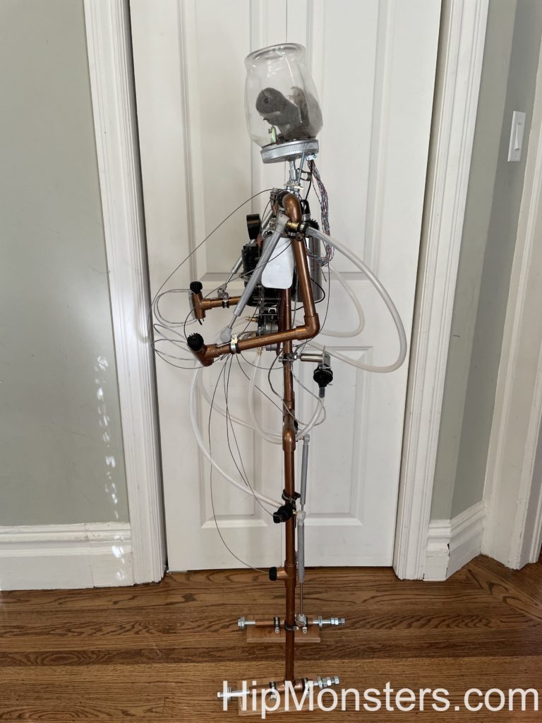
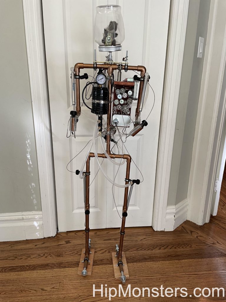
The image to the right is the completed robot. The starting images ended up not as good as we expected so the final image was the best to show how the tubing was used. First, we cut the pipes to the right size using one of us to figure out lengths arms, legs and spine. Then we assembled it and added feet to keep it stable as we worked.  The feet were harder than expected to get the right balance and weight. We used concrete bolts with extra washers as needed.

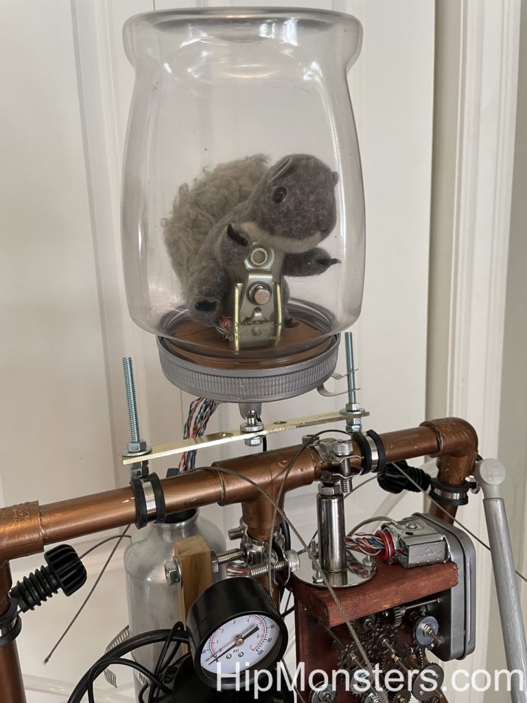
Then we assembled the PVC pipes and painted it with two coats.  The first was sliver; the second was bronze.  Next, we used an old security camera mount and attached a plastic jar on the neck. We added a toy squirrel inside and a few parts that looked like little controls for it. We named the squirrel Professor Brookenhoff.

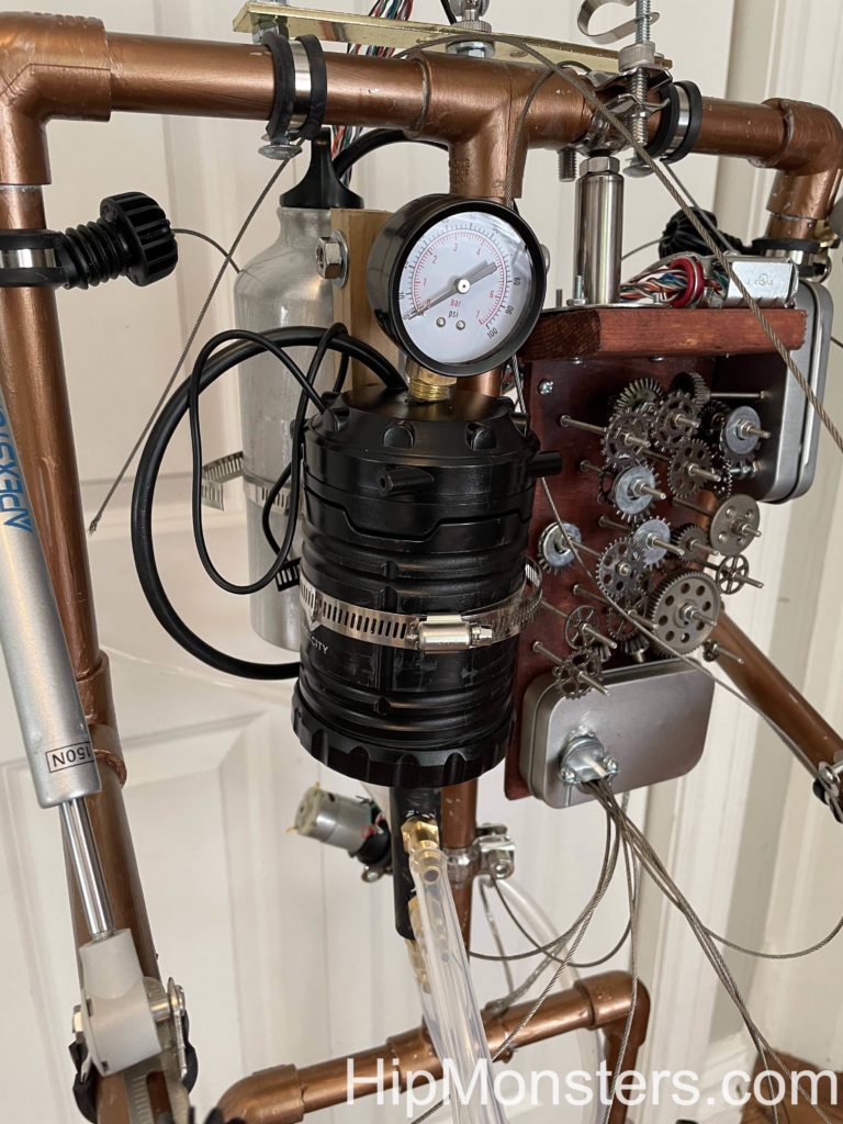
For a fake engine core we used an old battery powered lantern connected to an old water bottle.

Building the gear box for the steampunk inspired robot
Assembling the gear box

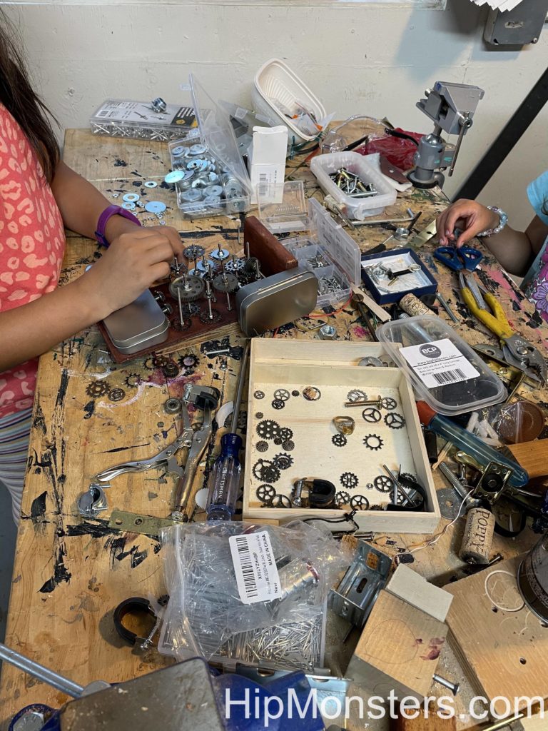
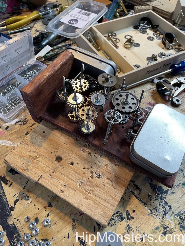
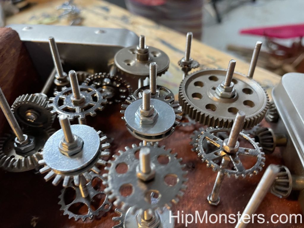
Now we started on the fake control box. To make is steampunk we used gears and only a few wires. Then we assembled the gears to control the robot. We used old wood as a base and stain and distressed it by hitting it with a hammer.

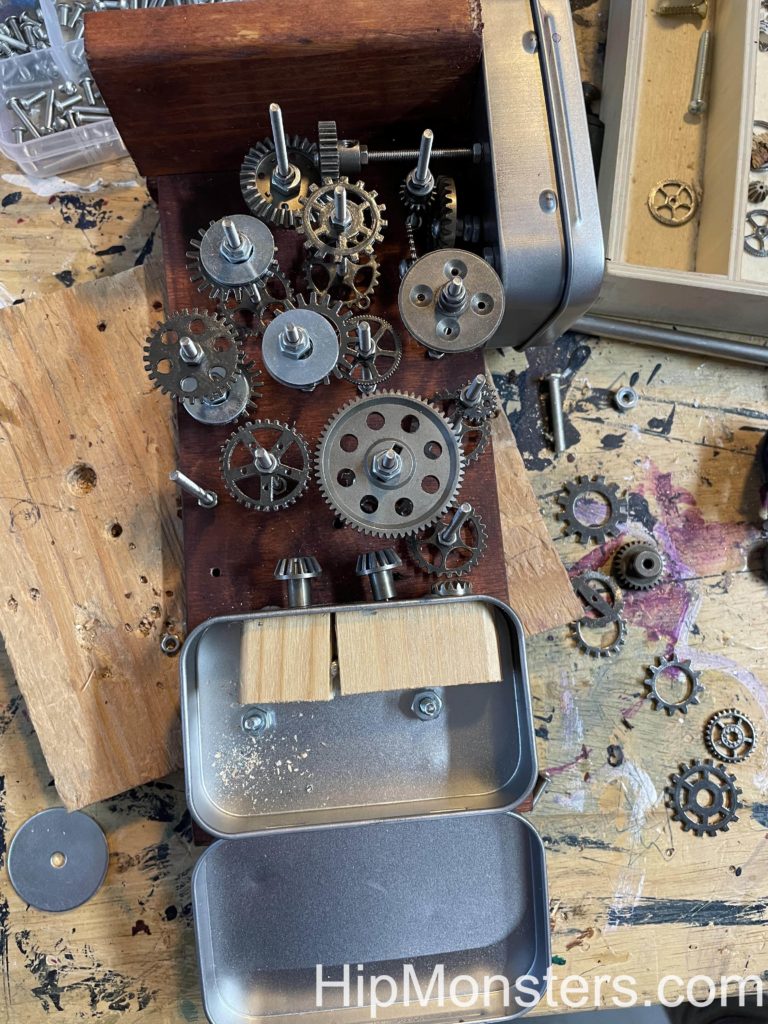
After that, we drilled a bunch of holes on the back and put thin, long bolts through them to create a framework for the gears.  Before we assembled it we laid out the gears on the table in the pattern we wanted then transferred the gears to the rig.  You must remember to lay out the gears in the opposite way you want them in the rig.

Gear box side view for steampunk inspired robot
Side view of the gear box

Here is a view of gears completed with the control boxes on each side.

The gears took the most time and ended up being a lot harder than we imagined.  It was difficult to screw the tiny nuts into place to give it a 3d look. Also, the bolts proved to be sharp. We attached some gears to the side of the control boxes so it would look like they actually controlled the gears.

Close up of the gear box to the steampunk inspired robot
Close up of the gear box

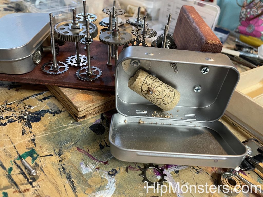
Then we attached a box to run the wirer through. We had a plan on the gears, engine, wire, pistons that we made before we started work that was our best attempt at design an honest working robot. The things we added is what Number 3 would have needed if it was real.

Side view of the gear box for the steampunk inspired robot
Side view

We then added a second box next to the gears for attaching the control wires.

Close up of the gear box for the steampunk inspired robot
Close up

Here is a close up of the gears. Getting a 3-D design is important to make it look real. Each gear needs two bolts. One on top and one on the bottom. Make sure they are tightly screwed together.

Back view of the steampunk inspired robot
Back view

Now we focused on putting on details that would make it look like Number 3 could move. Since it was supposed to be steam powered we used four left over pistons. We attached pneumatic tubing to the pistons then attached the other end to the engine. The idea is the power from the engine would create steam, and Professor Brookenhoff would give commands to the gears which would send the steam to the right piston to make it move.  The idea of the head came from Carmichael from The Umbrella Academy.

Feet for the steampunk inspired robot
Close up of the feet

As we added more details to Number 3, we also needed to add more heavy things to the feet for stability.

Close up of the head of the steampunk inspired robot
Close up of the head

A close up of Professor Brookenhoff piloting Number 3.

Close up of the chest of the steampunk inspired robot
Close up of the chest

A close up of the tubing from the engine to the joints.

Side view of steampunk inspired robot
Side View

Number 3 from side view. Here you can see the hands which also ended up being hard to make. Finally we made the hands out of wires and springs so it can hold things.

Front view of steampunk inspired robot
Front View

Here is the final completed robot.

Happy Creating!

Shape Shifting Toy Robots

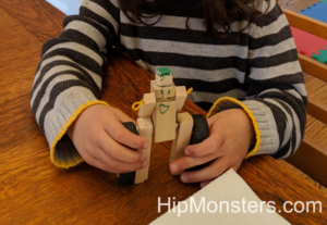
When the sisters team discovered Transformer comics (Go WindBlade!) they wanted a whole city of Transformers to play with. While that was way too expensive, they could build their own Shape-shifting Robots out of wood.

Supplies for a hand crafted DIY robot that transforms
Getting Started

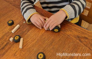
Borrowing from wooden dolls, we settled on a design with rubber bands attaching the arms and head to the body and a bolt to attached the legs enabling the robot to shift forms.

Making DIY wooden transfromjng robots
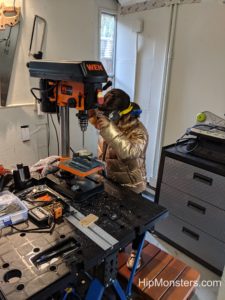
Drilling to holes

First we cut and drilled all the wood based on a working design.

Assembling a hand crafted DIY robot that transforms
Assembling Begins!

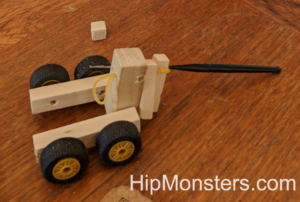
We used lego wheels for the robots that transformed into cars.

Fitting rubberband a hand crafted DIY robot that transforms
Fitting the rubber bands

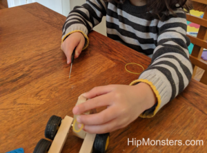
Attaching the rubber bands proved difficult.  We used a jewelry tool to thread the rubber bands through the holes in the wood (many broke in the process).

Assembling a hand crafted DIY robot that transforms
Final Touches

A few more adjustments.

A hand crafted DIY robot that transforms
The Robot is complete!

By using springs in the legs the robot can hold a standing position.

DIY wooden transfroming robots
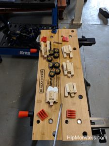
The assembly line

After we perfect a design, it was just a matter of creating a assembly line to crank out droids! We did some that turned into cars, some that turned into bugs, and some that turned in to other forms!

DIY Wooden Transfroming Robots.
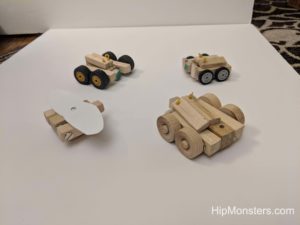
Transformed

The robots in alt form.

DIY Wooden Transfroming Robots.
Robot form

The robots transformed!

Happy Creating!