Mesocosms are controlled environments that simulate nature in an enclosed space. They are often used for experiments, but they are also a fun and convenient way to grow plants, because they are completely self-sustaining. In this article, we will teach you how to make a small DIY mesocosm.
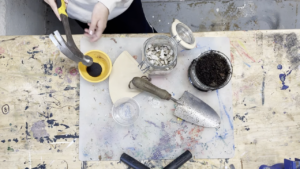
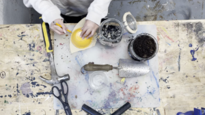
Materials:
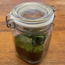
- An airtight transparent jar
- Water
- Small rocks or pebbles
- Charcoal
- Wet soil
- Organic coffee filter or Sphagnum moss
- Small plants and moss
- Parafilm (optional)
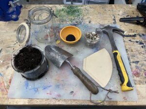
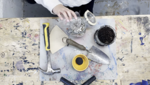
Tools:
- Scissors
- Shovel
- Hammer
- Mister (optional)
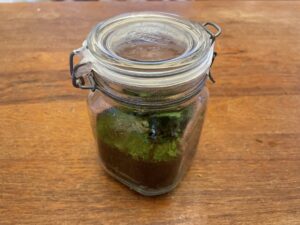
Step 1: Put a layer of pebbles about an inch thick at the bottom of the mason jar. This is for water drainage to make sure that the plants don’t drown
Step 2: Crush up some charcoal with the hammer until it is mostly a powder with some small pieces. The charcoal should just be enough to have a thin coating on top of the rocks. This will absorb moisture and prevent mold from growing.
Step 3: Make a barrier between these layers and the next ones using either an organic coffee filter or sphagnum moss. We used a coffee filter because we did not have any sphagnum moss, but if you have both, we recommend using the moss. If using the coffee filter, use the scissors to cut a circle out of it that fits perfectly in the jar. If using sphagnum moss, make a thin layer that completely covers the charcoal.
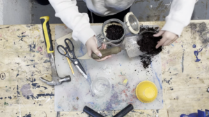
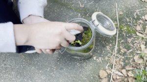
Step 4: Divide the remaining space in half and fill half of it with damp soil. If your soil is too dry, add water. This layer should be very thick but there should still be room for air on top and for the plants to grow taller. Don’t worry about having insects in the soil, they will not negatively effect the mesocosm, and are also self-sustaining.
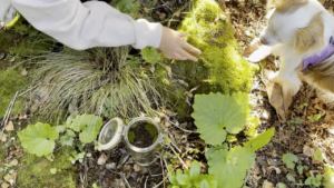
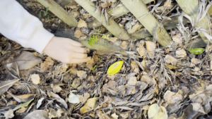
Step 5: Find some plants and moss. Make sure that your plants are not too big, because they will continue growing inside the mesocosm. We recommend using plants like ferns and moss that love high humidity environments, but you can use any. Once you are done, use a mister to spray it with water, or carefully water it. The goal is for the mesocosm to be sealed forever, so make sure you water it enough.
Step 6: If not using Parafilm, skip this step. Cut the Parafilm into strips almost an inch thick. Then peel off the backing and carefully stretch it as far as it can go without breaking. Stretch it around the rim of the jar and use several strips to make sure it is fully sealed. It might take a few tries to get this right.
Step 7: leave the mesocosm in a place with sunlight. The plants need sunlight to grow, and the heat will help make the mesocosm’s own water cycle.
If the mesocosm has any problems, like it doesn’t have enough water, or starts growing mold, you can unseal it to fix the issue before resealing it.
Congratulations, you have completed you DIY mesocosm!

Happy creating!


 Inspired by