Here are some of our favorite spring flowers in our yard from this spring! These range from flowers we planted in the yard to wildflowers that appear every year.
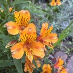
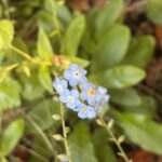
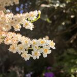
The orange flowers on the very left are orange Alstroemeria lilies, also called Peruvian lilies or Inca lilies. They are bulbs with long stocks and bright leaves that flower for a long time, from early spring to summer, and are one of our favorites. The ones in the middle are in the genus Myosotis, also known as woodland forget me nots, have clusters of small light blue flowers and fuzzy oval shaped leaves. They flower in spring and are self seeding. On the very right, we have Prunus serotina, commonly called black cherry. It has dark rubbery leaves and clusters of small white flowers. This is the first year that it flowered!
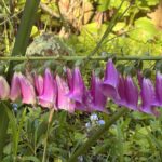
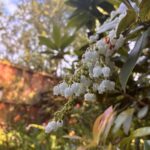
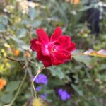
Here on the left we have Digitalis purpurea, also known as foxglove flowers, which flower from early spring to the start of summer. They have fuzzy green leaves and a cluster of bell shaped flowers on a long stalk. The flowers in the middle are Pieris japonica, also known as Japanese Andromeda, which flowers for a long time in spring. It has flowers resembling lilies of the valley, with old leaves that are tough and green, and new leaves that are soft and bright red. The final flower here is in the genus Rosa, known as roses, which flower in early spring, and sometimes multiple times a year. They have small bright flowers with dark green leaves and thick stems with thorns.
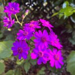
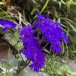
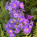
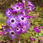
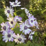

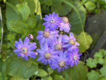
These spring flowers are all cineraria flowers, which flower late spring and summer. Their colors can range from bright pink to blue to purple, and often have flowers with multiple colors. They have large bright green leaves and have seeds that look like dandelions. We keep the dried stems up so the seeds can spread, so we will have many flowers every year.

This flowers is a type of lily, in the genus Lilium. They have large dark pink blossoms and thick petals.
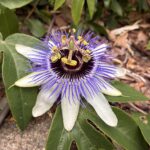
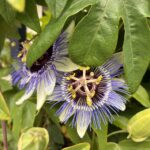
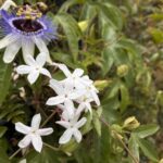
The first two flowers here are passion fruit flowers, in the Passiflora family which flowers all spring. The last one is Jasminum officinale, called white jasmine or pink jasmine. It flowers from late winter to spring and has very fragrant blossoms. These two are both vines and the passion fruit flowers grow especially well in the climate. This is also the first year that we had these flowers!
We live in San Francisco, so our weather is often foggy with occasional sunnier days or rain. Most of these flowers get part sun, and the temperature rarely gets over 80 degrees.
Hope you find inspiration!


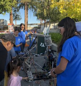
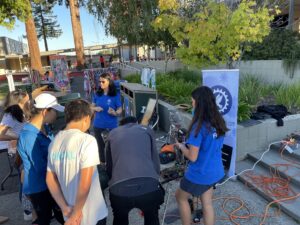
 Now we can keep track of our robots as they explore the world!