This post is an old one we forgot to publish a while back. Currently, Number Three is controlled by a script that is run on a Raspberry Pi sending commands to an Arduino. But originally Number Three was controlled by a wireless relay switch. We used wireless relays at first because they are simpler and we could just focus on the mechanics of the robots. As our robots got more complex, we had to migrate to Raspberry Pis. This post is a good overview of wiring a relay and even if outdated gives good insights. Also, a wireless relay may be useful in other situations.
Please note, this material is provided for informational purposes only and is not a guide on how to create the designs. Please take a look at our disclaimer.
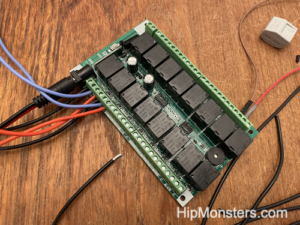
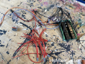
Here is a 12-volt, 16 relay wireless board. It is typically used for lighting but we have other purposes in mind- robots! To begin here are some basics. To control motor you change the power going it. A motor needs positive (red wires) and negative (black wires) energy to work. A relay controls power going to an engine. When wiring a relay the wire that gives the signal (what tells the relay to be on or off) is usually a color other than red or black. In this case the color is light blue.

Honestly there is not too many parts to this build just the relay, linear actuators, wire nuts and a lot of wires. We recommend doing the build in an area easy to clean and free from pets. When you cut the wires little bits of wires can fall to the floor may end up in the foot o a pet.
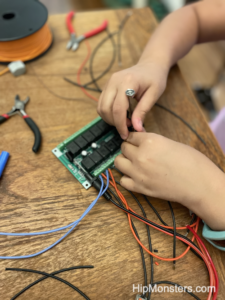
The wiring for the relays proved to be more difficult than we thought because the wires were slightly thinker than the connection wanted. We had to twisted them tightly to fit them in. If you are buying wire go with a thin grade.
When doing a wiring job of this scale, over 64 wires, it is best have a plan laid out before starting and if possible divide the labor. Our plan was to wire in order or wire type (signal, positive, negative, output). To make it easy we cut all the wires the same length. To attach the wires we used wire nuts but have migrate to using lever connection nuts for quick builds. The wire nuts proved to be too finicky and we don’t recommend them until the final build.
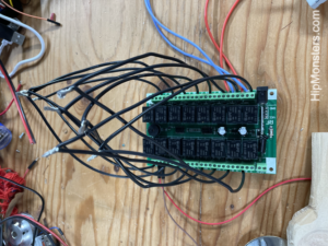
Here is a pile of pre-linked positive wires. Since we wanted to control a linear actuator we need to use two relays to control on the power. To make an actuator extend and retract you need to you flip positive to negative, this is called reversing polarity. But one relay can on turn power on and off. So to be able to reverse polarity we needed to wire XOR logic gate. This is a good overview of how to control linear actuators and here is a good diagram on a XOR XOR logic gate.
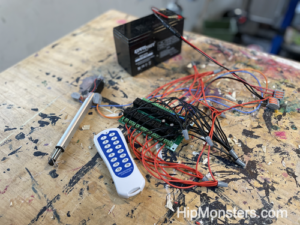
Here is the completed relay ready for testing. Make sure all the wires are screwed in tightly and no fray wires are touching before pugging in the relay.

And what better way to test than knock something over and make a big mess!
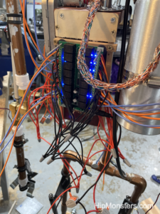
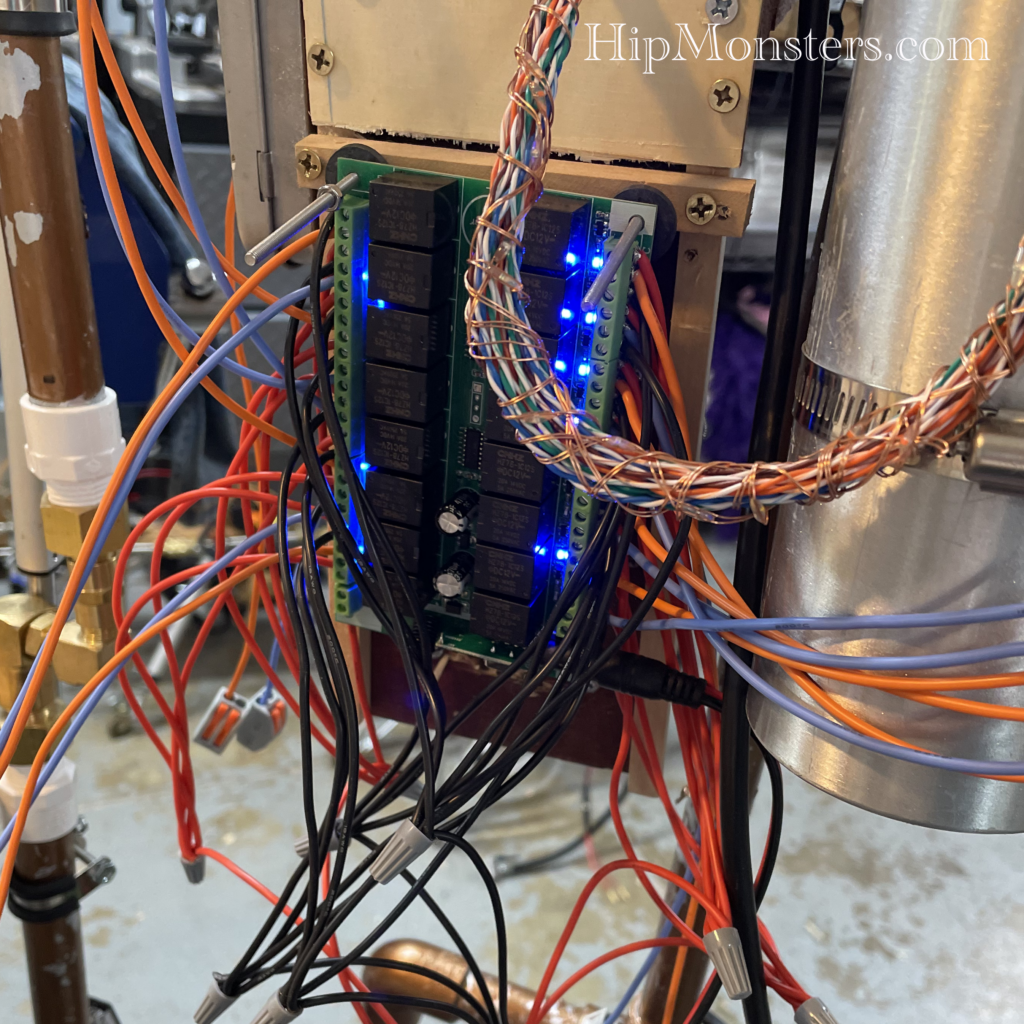
Here is the new controller installed on the back of Number Three. Since we are aiming for a steam punk robot the mass of wires is exactly the look we wanted.
Happy Creating!