Sensor Array Mounts Part Two

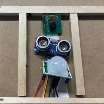
This is our working solution for making secure sensor array mounts for our robots. Because the first one failed, we made many changes based on what worked well and what didn’t.

Please note, this material is provided for informational purposes only and is not a guide on how to create the designs. Please take a look at our disclaimer.

The Video below shows us making a model for the sensors.

YouTube player
Now we pour silicon over the clay model to make a model.
YouTube player
Once the silicon is dry we removed the clay model.
YouTube player


To get the metal finish we mix in brown dye and copper pounder into the resin then put it into the cast.
YouTube player


It you look closely you can see the resin flowing as it dries.
YouTube player

We carefully remove the resin from the molds.

YouTube player

‘A bit of light sanding finishes it off.

YouTube player
Now we attach the sensors.
YouTube player
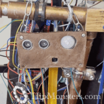
Finically, Number Three has a stable sensor mount!
YouTube player
Happy creating!

Sensor Array Mounts Part One

To make a sensor array mount for the robot, we wanted to try using resin molds. This experiment did not work as intended, but we wanted to share how our experiment went and maybe find a use for the resin pieces in the future. Here is a link to our working solution.

Please note, this material is provided for informational purposes only and is not a guide on how to create the designs. Please take a look at our disclaimer.

First, we laid out our basic design of the sensor array mount using square wooden dowels. Then we traced the design using a markers on a piece of plywood to help guide us later.

Next, we glued the dowels together using hot glue to create a frame. We made sure the joints were tight and leak proof so the resin wouldn’t spill out.

Then we glued the mold to the plywood and put an extra layer of hot glue on the outside. We lined everything with a mixture of one part vegetable oil and one part dish soap to help the resin would separate from the mold. Then we poured the resin into the mold.

We store the mold in a secure location making sure it was laying flat.

While the process did give us a cast, the mold had to be destroyed to get the resin out. The homemade releasing agent did not work, and caused the clear resin to turn green and oily. The design also ended up not aligning as well as we needed. For making resin molds, we recommend not using dish soap or vegetable oil because it will interfere with the resin’s color and make it oily and sticky even after it dries. However, it did make it easy to separate the resin from the mold. We also learned to not make the mold out of wood. Back to the drawing board!

Happy Creating!

Number 2’s and Number 3’s New Legs

From last year’s Bay Area Maker Faire we learned a lot about what is the right and wrong way for our robots to move. Our first designs did not work well on the rough and uneven surfaces, and our bi-pedal design fell over before the gates even opened. From that experience, we have opted for a centaur design for the new legs, leveraging a more powerful engine, a collapsible design, and gears.

Please note, this material is provided for informational purposes only and is not a guide on how to create the designs. Please take a look at our disclaimer.

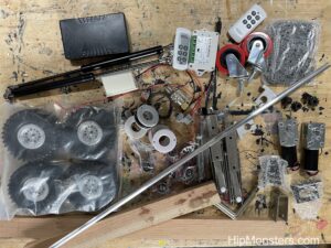
The legs are more simple overall but still require a lot of parts. We moved to using hardwood for the critical components for its strength.

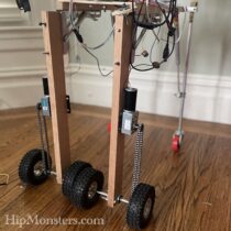
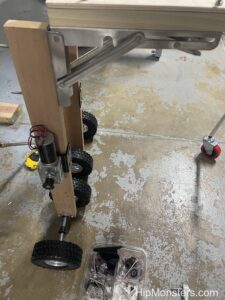
Our design changed a lot from the one at last year’s Maker Faire. First, each leg has two wheels connected to a axel. The motor turns the axel via a chain. The biggest change is the legs now fold and unfold to make transportation easier.

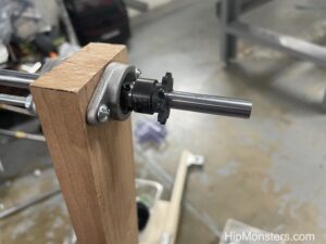
Here is a close up of the finished axel on the end of the leg with one of the gears.

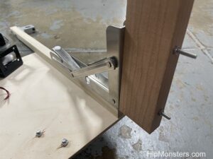
Here is one of the leg connecters that allows the new legs to fold for travel. They can lock in place when the robots are standing or walking.

YouTube player

Here are the legs with the wheels attached.

YouTube player
YouTube player

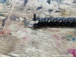
Here is a close up of the chain with one of the pins almost removed.


YouTube player

YouTube player
YouTube player


Happy Creating!

Number Ten Gets A Screen

We have started upgrading all our robot to run the new RobotFreedom.AI framework. For Number Ten, the main missing piece was a screen. Some of our early designs were not built with a screen in mind and adapting the design has taken a few iterations.

Please note, this material is provided for informational purposes only and is not a guide on how to create the designs. Please take a look at our disclaimer.

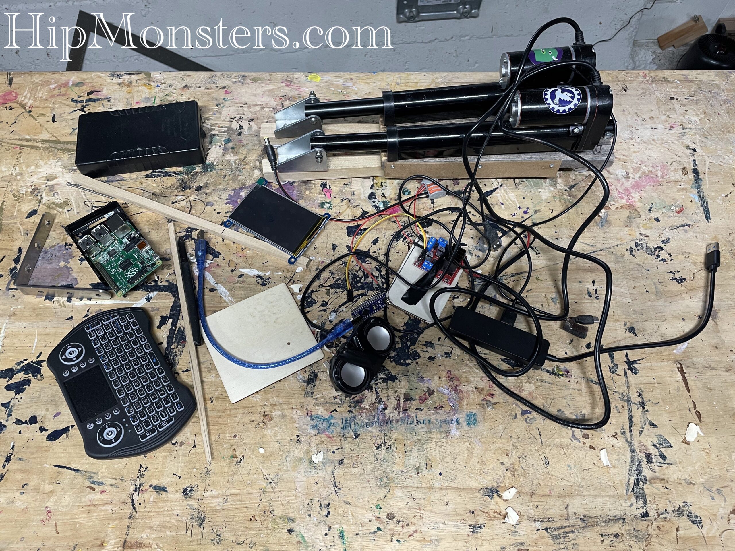
Here is a list of some materials and components used:

Number Ten was a tricky design to fit a screen on and keep to its original design. After many attempts we settled on using a L-Bracket placed at the front the body to mount the screen.

Now we reassembled the legs onto the body. Number Ten was one of several experiments the Hip Monster’s sister team built to come up with the most unusual way to move a robot. The robot moves forward, left and right by sliding one foot forward. On the bottom of each foot is edge shaped gripers that provide traction when pushed against but slide when pushed forward.

The screen is light enough to only need a few attachments to hold it in place. For added support we used a wire at the top of the screen to keep it secure while moving. Number Ten has never fallen forward so we need less protection for the electronics and screens than some of out other designs.

Our we assemble the various components Number Ten will need. We recommend using a usb hub  for the wireless keyboard dongle. If you have several robots you will want to reuse the keyboard and will need quick access to the dongle. Typically, once we settle on a final layout for the RaspberryPi it is in a secure but difficult to each place making removing the dongle difficult. For people with less than perfect eye sight we recommend using a magnifying glass and bright lights when connection the GPIO pin to the RaspberryPi.

YouTube player

And here is a quick video of Number Ten display screen working. It is a light weight version of our main display better suited for older RaspberryPis.

YouTube player

Happy creating!
Number Nine is Rewired

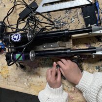
We are learning weight is everything when it comes to good performance from our robots. One of our best jumpers, Number Nine, used splicing connectors that had very useful push handles but were way too heavy for continued use.

Please note, this material is provided for informational purposes only and is not a guide on how to create the designs. Please take a look at our disclaimer.

The old connectors were perfect when we were prototyping designs, but once we settled on a wiring diagram it was time to move on to the much lighter push-in designs. The video below is a sped up video of one of the Hip Monster’s sister team (age 13) rewiring Number Nine with the new connector:

YouTube player

And now for testing! Here is a video of Number Nine is back in action and ready for more upgrades:

YouTube player

Happy creating!