Maker Faire 2025

We are very excited to announce HipMonsters.com will be presenting RobotFreedom at this year’s Bay Area Maker Faire, September 26 through September 28th at Mare Island!  We have been training our emotional robots for over a year, living with them, playing with them and watching them grow. Come see our robots in action live! 

Here is a recap of the 2024 Bay Area Maker Faire to give you a preview of what to expect. These are some of our favorite exhibits, from an underwater robot explorer to a giant inflatable cuttlefish car.

Bay Area Maker Faire

This is the Maker Faire Bazaar, where visitor can find all sorts of handmade goods, like dice, pottery, and even 3d-printed hot chocolate.

Metal orrery at Bay Area Maker Faire

This is a big working model of the solar system that is the size of a room. All of the planet’s orbit times are proportional to the real ones.

Miniature house at Bay Area Maker Faire

This is a small model of a bakery with working lights and miniature baked goods.

battle bot at Bay Area Maker Faire

This is an old battlebot, complete with two giant spikes in front and four googly eyes (Maker Faire 2023).


DIY robots at Bay Area Maker Faire

This is the Humanoid Robot Comedy Show. These robots can move their faces to show facial expressions and look you in the eyes while they tell jokes.

Steampunk DIY robots at Bay Area Maker Faire

This robot is built for battle. This is one of the robots that fights in an arena against other robots. It is remote controlled and has arms that can swing around.

Dalek at Bay Area Maker Faire

This is Dalek FAX, a remote controlled model of a Dalek that moves and talks.

Under water robots at Bay Area Maker Faire

This small robot is built by ROV Tour: Underwater Robotics Adventure. They are remote controlled and have cameras that can show footage of its underwater adventures.

After.AI winning Maker Faire prize

And the award winning After.AI whose 3D printed mechanical flip signs were so fun to watch!

Gear art DIY robots at Bay Area Maker Faire

This amazing clock uses a whole wall full of gears to tell time.

Metal fire insect at Bay Area Maker Faire

This is a part of Serenity, an art exhibit showing three insects that shoot fire at a press of a button (Maker Faire 2023).

inflatable art DIY robots at Bay Area Maker Faire

These are parts of Astro Botanicals Space Garden, which is a collection of glowing handmade inflatable plants.

Inflatable art DIY robots at Bay Area Maker Faire

This is Sepia Lux, a giant inflatable cuttlefish car that lights up. The tentacles and the fins of the cuttlefish can move, and the eyes can change colors.

Truck at Bay Area Maker Faire

This is a truck inspired by a beetle complete with wings and a bright green shell.

Drivable peacock at Bay Area Maker Faire

This is a peacock vehicle that lights up and moves.

We are looking forward to seeing you all at this year Bay Area Maker Faire!

Hope you find inspiration!


Securing Wires on Number Two and Number Three

We take Number Two and Number Three on the road a lot. While we are now experts at rewiring them after a long road trip, we started testing new ways for securing wires while still letting kids see how the robots were put together. After many designs, we settled on using clear silicon pneumatic tubes. The tube protect and secure the wires but still allow people to see how the wires attach.

Please note, this material is provided for informational purposes only and is not a guide on how to create the designs. Please take a look at our disclaimer.

YouTube player

This video shows us taping the wires.

YouTube player

This video is us splitting the clear tubes down the middle to fit in the wires.

YouTube player

This video shows the process of wrapping the wires in the tube.

YouTube player

This is the final result.

Happy Creating!

Number 2’s and Number 3’s New Legs

From last year’s Bay Area Maker Faire we learned a lot about what is the right and wrong way for our robots to move. Our first designs did not work well on the rough and uneven surfaces, and our bi-pedal design fell over before the gates even opened. From that experience, we have opted for a centaur design for the new legs, leveraging a more powerful engine, a collapsible design, and gears.

Please note, this material is provided for informational purposes only and is not a guide on how to create the designs. Please take a look at our disclaimer.

The legs are more simple overall but still require a lot of parts. We moved to using hardwood for the critical components for its strength.

Our design changed a lot from the one at last year’s Maker Faire. First, each leg has two wheels connected to a axel. The motor turns the axel via a chain. The biggest change is the legs now fold and unfold to make transportation easier.

Here is a close up of the finished axel on the end of the leg with one of the gears.

Here is one of the leg connecters that allows the new legs to fold for travel. They can lock in place when the robots are standing or walking.

YouTube player

Here are the legs with the wheels attached.

YouTube player
YouTube player

Here is a close up of the chain with one of the pins almost removed.


YouTube player

YouTube player
YouTube player


Happy Creating!

Maker Fest at Ecole Bilingue in Berkeley

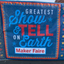
The Hip Monsters team was thrilled to be invited to a Maker Fest last week at Ecole Bilingue in Berkeley, CA. Ecole Bilingue is a preschool to eighth grade French immersion school focused on preparing their students to make a positive impact on the world.

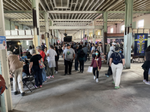
We had a wonderful time at the maker fest and it was amazing to see such talented makers and dedicated students. The event had great food (including handmade boba tea), a fun crowd, and an exciting lineup of makers. It was a beautiful day in Berkeley which added to the cheer.

Below are just some of the makers at the festival.

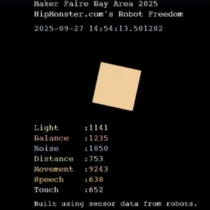
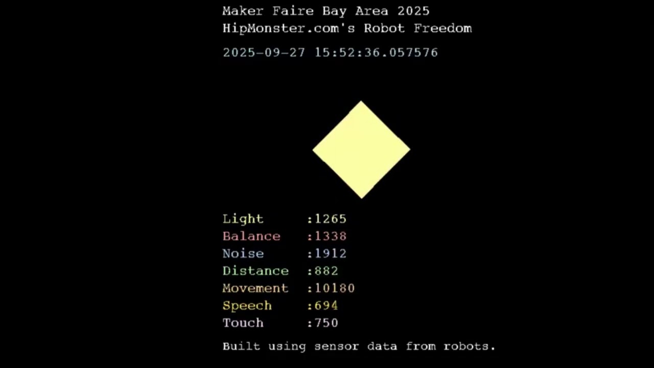
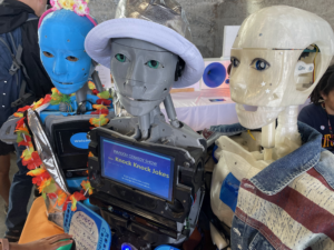
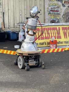
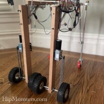
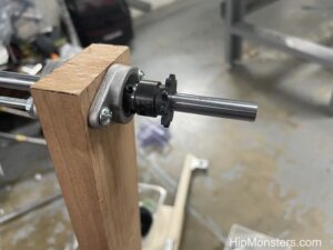
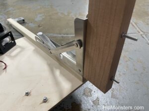
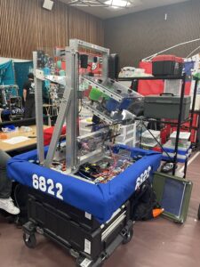
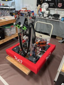
Hip Monster’s Robot Freedom

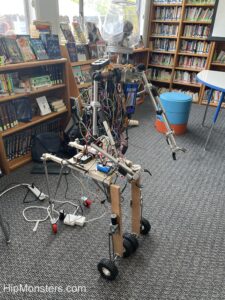
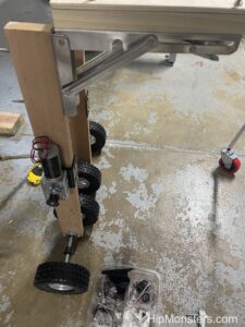
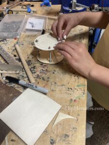
We were there with Number Three of RobotFreedom, who got a chance to test out her new legs. We will have a post in a bit on her leg redesign. The legs worked well and the batteries lasted longer than we anticipated.

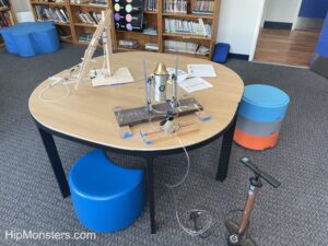
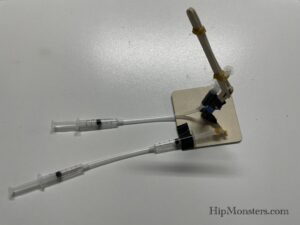
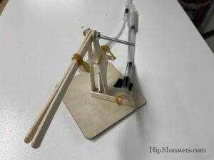
We also brought our pneumatics demonstration which is an ideal place to start kids (and adults) on robotics.
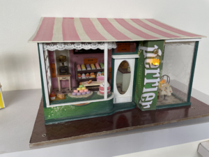
The Sewing Corner 

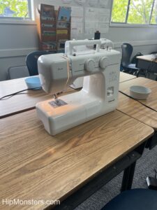
There was a great sewing section with helpful makers who quickly got even first time sewers make a tote bag.

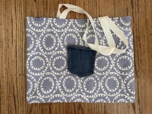
Here is a finished toto bag! We have already put it to good use storing cat toys.

Magnification Mayhem vs. Resolution Rumble!

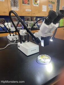
George and Janai Southworth from the San Francisco Microscopical Society had a fantastic demonstration of microbiology. They showed how different filters and lightning impacted what could be viewed through the microscope.  Below is a petri dish of bacteria waiting to reveal its secrets.
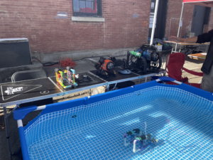
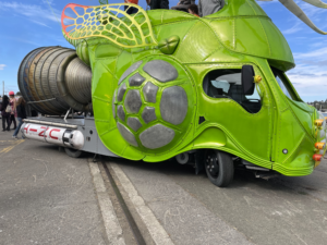
Solar Racing Car

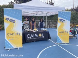
Members of the UC Berkeley CalSol Solar Racing Car were there giving us the inside scoop on their upcoming race in Nashville, TN. Every few years the car is completely redesigned and rebuilt using the most up to date technology. 

3-D Print Making

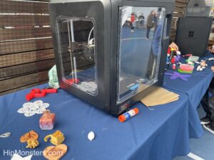
There was 3D printing space with a great collection of designs and examples. All the designs were coded by kids!

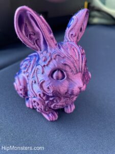
Here is our favorite creation, a 3d printed pink rabbit.

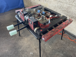
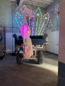
Bike Powered Smoothie Machines

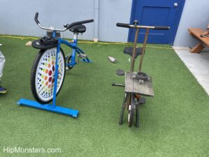
The bike powered smoothie machines were steampunk inspired pieces of art. They were designed and made by the talented students at Ecole Bilingue. They also are a great way to make sure you earn those calories in the smoothie. Every household should have one of these!

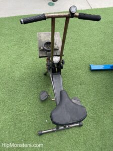
The designs are modified stationary bike with blender connected to the front wheel.

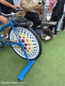
Here are the bikes in action making a smoothie.
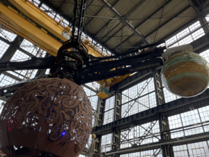
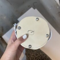
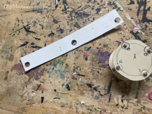
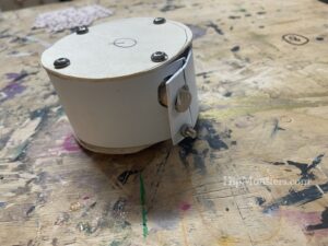
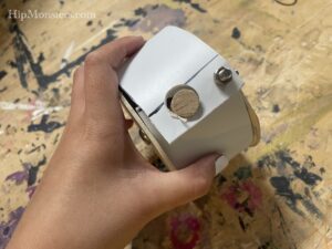
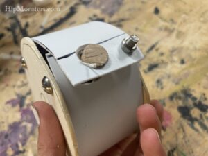
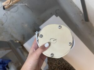
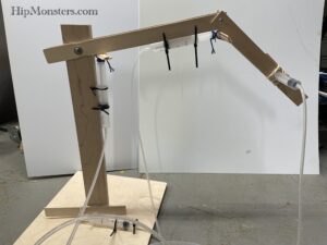
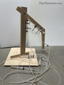
Painting Robot

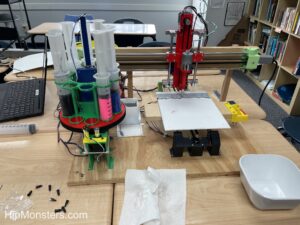
They even had a robot making art! It was fun watching the robot as it dutifully created its next masterpiece.

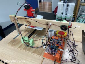
Here is a view of the business end of the painter bot.
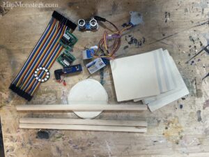
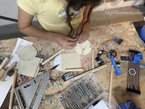
Space Wars

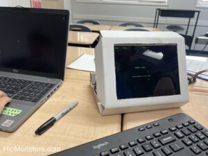
And last but not least, a RaspberryPi powered game console designed and built by one of the students. The compact design had custom made controllers that allowed for two person games.

The stand was a clever design using a cardboard box as a case neatly cut so it looked.

Thank you so much to Ecole Bilingue for inviting us to the maker fest! We would love to participate in more of your events in the future.

Hope you find inspiration!

Girl Genius Dingbot Robot Part One

We decided to finally make an attempt to build a Dingbot robot based on the girl genius web comics.

Please note, this material is provided for informational purposes only and is not a guide on how to create the designs. Please take a look at our disclaimer.

Our design is based on the first BingBot, a small robot similar to a pocket watch. Below is a image of a GirlGeniusOnline Dingbat in action.

As the series continue she create a variety of different BingBots and even Wingbots.

After we have settled on a design on paper we like laying out all the components on our workbench and start visualizing how the pieces fit together and to make sure we have all the parts we need.

We made the design as small as possible but still fit all the electronics including a RaspberryPi Nano. We wanted the design to be a fully functioning computer. The idea was when it is not running about it can be used to play music or video games.

The front and back to the robot are plywood circles that will serve as bases for all the electronics. To make sure the two sides align, we clamped two pieces of plywood together and used coping saw. To smooth out any irregularities, clamped them together again and sanded them repeatedly.


We used 2 inch bolts to separate the front and back plates. The is the smallest width that will still be able to hold all of our electronics. After repeated measuring, we drilled the holes while they were still clamped. This assured the bolts would align. Since the bolts are part of the atheistic of the robots it is important to get the positions correct.

We used three nuts and four washers per bolts to acts as spacers. To keep the bolts from loosing we used lock bolts (which can prove difficult to put on) and a pneumatic tubing in between the top and bottom bolts. We have used pneumatic tubing as spacers before in our robot designs and it works great even after years of use.

Once the two plates were secured we cut a strip of plastic to seal the gap. We thought using the side to access the components would be a unique and useful design. Normally, we prefer to have most of the electronics exposed but dingbot has a clean and elegant design. We recommend testing your layout of a sheet of paper first before cutting the holes in the plastic.

After a few trial and error we managed to secure the plastic strip. The first one broke so the second time we heated it with a blow dry to make it more flexible.

Down the center of the robots is a wooden dowel which will server as the spine for the robots.  The legs and arms will both be anchor to the spine.

Here is a bottom view showing the spine.

We are not 100 percent happy with how the plastic strip pops out but we will try applying low heat again and try and mold it into shape.

Although you cannot see them, the design fits a RaspberryPi Nano, two motors, h-bridges, tons of wiring and a battery neatly.

Next step is to design the legs! We are leaning towards a toy robot inspired design.

Happy creating!

First Robotics Competition in SF

We had a lot of fun at the First Robotics Competition at St Ignatius College Preparatory in San Francisco CA. We cannot think of a better way to spend the weekend than watching teams of highly skills robotics engineers compete for fame and glory!

Above is a photo the entrance to St Ignatius located in the heart of the Sunset district in San Francisco.

Below is a video showing one set of the robotic competition.

YouTube player

The goal is for your team to finish as many tasks as possible before the time runs out. Each team has three robots: two that are focused on competing tasks and one that tries to disrupt the other team’s robots. The court is divided in two with each team having one side as their home where they perform their tasks. The tasks are placing the tubes in a slot, throwing a ball and lifting themselves up at the end of the round.


Here is a close up of one of the robots, number 6822. It is amazing to see how many different and creative designs the teams come up with. For example, some receive the tubes from feeding machine while others scoop them up from the floor.

Here is another robot, 7667, waiting to be serviced.

Above is a photo of a typical repair station. Like with the robots, each team has their own layout and collection of tools optimized for their robot’s design. We had serious tool envy as we walked through the pit.

While none of our photos have people, the event was crazy crowded. We made sure to exclude people when taking photos, so missed about half of the teams at the events. Below is a sample of some of the teams there.

The Otter Bots.

The Aztechs from Alameda, California.

And team 846 with the absolute coolest pin dispenser ever!

The Breaker Bots.

The Pirate Robolution!

The Bot-Provoking.

Bora Robotics from Türkiye!

Blue Magpies from Taiwan!

Find your inspiration!

Pneumatic Robotic Arm Workshop

This pneumatic robotic arm workshop is design to introduce basic concepts of robotics and making to grade-school students. The design is based on ones used in middle school and high school robotic competitions. We have created a simplified version for one-time workshops with kids of all ages.

Please note, this material is provided for informational purposes only and is not a guide on how to create the designs. Please take a look at our disclaimer.

The two main science concepts are:

  • Leverage: A lever is a simple machine consisting of a bar that pivots on a fixed point (fulcrum). Levers are used to amplify input force. The robotics arm requires placing the syringes in positions that exploit leverage. You can find out more here.
  • Pneumatic:Pneumatic power uses compressed air as an energy source. Basic components of a pneumatic engine are: reservoir, pump, value and cylinder. In this workshop the syringe is the pneumatic engine. Pneumatic power is widely used in robotics and industry. Here is a link for other project ideas. 

Required Supplies:

Each student will require:

  1. x4 syringes
  2. x2 4-inch piece of tubing
  3. 1  4×4 piece of wood
  4. x5 Popsicle sticks
  5. X2 nut and bolts

The photo below is the full-scale model used in high school competitions. It requires 2-3 students to control. One of the Hip Monster sisters built it at a Sacred Heart Robotics Camp in San Francisco, CA.

Here is a side view with the arm down.

The competition involves stacking blocks and the score is based on time it takes to move all the blocks and height of the stack. Controlling the arm is a true team effort with 2-3 students working together to move the arm. The winning design not only requires good engineering but perfect team work. Engineering competitions are ideal ways for kids to develop technical as well as social skills.  Below is a video of the arm in action:

<video of it working>

For our grade school work shop we choose a smaller and simpler design that only required one student to control the robotic arm. You can still have a team competition with two students per robot (one controlling each syringe) if desired.

Below are several views of our simplified design. Instead of zip ties we use rubber bands and tape.

Here is a view from above. This design does not use hot glue and is suited for all ages.

This is another design suited for more advanced students.

Here is a side view showing the placement of the syringe in the middle of the base to provide better range of movement.

In the video below one of the Hip Monster’s sister’s team does a quick build of an arm.


YouTube player

Here are the step by step instructions:

  • Drill a hole in the center of the square plywood which will be the base for your robotic arm.
  • Now push a bolt through the hole and secure it using a nut. The bolt will be the support for your arm.
  • Drill a hole on one end of four popsicle sticks.
  • Use the two popsicle sticks placed on either side of the bolt with the holes on the top.
  • Secure using rubber bands making sure to let it pivot.
  • Secure a syringe to a popsicle stick. This popsicle stick provides leverage helping move the arm.
  • Use rubber bands instead of tape or glue. Rubber bands let the mechanism flex as the pump extends pushing the arm.
  • Attach the piping and connect another syringe.
  • Adjust the two syringes so when you depress one the other extends.
  • Attach one end to the popsicle stick using a rubber band.
  • Next secure the other end to the edge of the base using tape.
  • Slow depress the syringe pump your arm will move!
  • Now attach two popsicle sticks to the top of the arm.
  • Secure with a bolt and nut.
  • Secure the syringe pump to the forearm with rubber bands.
  • Now attach the syringe base to the arm using tape.
  • Connect the other syringe.
Now you pneumatic robotic arm is complete!

To improve performance you can turn your pneumatic robot to a hydraulic powered one by just adding water! You can get more information here.

YouTube player
Happy Creating! 

Updates to RobotFreedom.AI

Since our last update at Maker Faire, we’ve made significant improvements to our robot lineup, focusing on increasing autonomy, human interactions and emotional expression. Core to this is our AI framework, RobotFreedom.AI now available on GitHub.

The design principle for our autonomous AIs ():

  1. Runs completely locally on a RaspberryPi (no third-party API call out)
  2. Has distinctive personalities based on the big 5 personality traits
  3. Learns from interactions (initiated when in sleep mode)
  4. Makes informed decisions based on a knowledge graph
  5. Can carry on a conversation between themselves and with a human

To achieve this we used an Agentic AI framework rather than just tapping direction into a chat bot. By having a core AI that was designed to meet our specifics goals we had more control of its behavior and could also directly see how the AI worked in real-time which provide to be a great educational tool.

One of the key upgrades is the addition of machine learning algorithms, which enable the robots to learn from their interactions and adapt quickly adapt new situations. This allows them to become even more autonomous in their decision-making processes, making them more efficient and effective in completing tasks.

We’ve also made notable strides in expanding the robots’ interactive capabilities, incorporating features such as voice recognition, gesture control, and tactile feedback. These enhancements enable users to engage with the robots on a deeper level, fostering a more immersive and engaging experience.

Some of the specific updates include:

* Advanced sensor arrays for improved navigation and obstacle detection

* Enhanced machine learning algorithms for adaptive decision-making

* Voice recognition and speech-to-text capabilities

* Tactile feedback mechanisms for haptic interaction

These updates have significantly enhanced the robots’ autonomy, interactivity, and overall user experience. We’re excited to continue refining our designs and pushing the boundaries of what’s possible with robotics and AI.

We have been busy working on our next release of our robot software platform

Major features:

  • Robots can coordinate actions using web socket communication
  • Dedicated http server for each robot
  • Added Piper TTS for voice
  • Added Vosk for speech recognition
  • Added Ollama and LangChain for chat bot.
  • Improved random movement generator.
  • Tons of bug fixes
  • Improved debug mode
  • Low memory mode for RaspberryPis 1-3

Tested on OsX and RaspberryPi 1-5.

You can see our Robotic AI platform in action here.

Happy creating!

Arduino Robotic Controller Software Update

This post will help you write the code for the robotic controller. The RobotFreedom robots are controlled by two code bases. The first runs on a RaspberryPi and is written in Python. You can read more about it here. The second code base controls the movements and lights on the robot. It is written in C and runs on a Arduino. This article will get you started on developing with that code base. You can download it GitHub.

Please note, this material is provided for informational purposes only and is not a guide on how to create the designs. Please take a look at our disclaimer.

The movement controller is designed to be light and simple compared to the main AI code-base and is ideal for a beginner. The focus is to provide an interface for a human or AI to control a robot’s moving components (arms, legs and wheels). We use a Arduino Mega Board because it has a plenty of digital pin to attach our components to. Below is an image of a Arduino Mega board.

Arduino’s can be controlled via serial communication through a USB port or you can code it to run independently. Our robotic walkers are controlled only by an Arduino. This project is intended to be controlled by an AI installed on a RaspberryPi.

The purpose of the program is to receive incoming messages and perform the requested action. For example ‘a’ means raise the left arm. When the program receives an ‘a’ command it sends a command to a H-Bridge which then send power to a linear actuator to raises the left arm.

To start, install the Arduino IDE on your preferred development OS. Linux, OXS and Windows is supported. You can get the code here.

Next, download the required library and copy them to your development folder.

Adafruit_BusIO
Adafruit_I2CDevice
Adafruit-GFX-Library
FastLED

Launch the Arduino IDE and from the menu bar select:
Sketch>Include Library>Add Zip Library…

Launch the Arduino IDE and from the menu bar select:
Sketch>Include Library>Add Zip Library…

Then point to one of the zip files you have downloaded. Repeat for each required library.

To open the project, double click on the movement_controller.ino file and the Arduino IDE should automatically launch. If it does not launch you can load the sketch by selecting File>Open then navigate to your project file.
Now choose a board type. When you connect your Arduino board it should be auto-detected by the IDE. For some brands you may have to manual select it from the combo box. For off-brand Arduino we recommend searching forums for the best match. Many specify incorrect boards in their descriptions.

Next select >Sketch>Verify Compile. At the bottom of the IDE a console will appear and provide a detailed log. If you missed any libraries you will receive an error message. Loading any required libraries and try again.

Once the code is compiled select sketch>upload to deploy your code.

Below is a list of the components the code can control:

H-Bridge
FastLED
Linear Actuator

The image below is the wiring for the Arduino:

To test select Tools>Serial Monitor from the main menu. At the bottom of the IDE a new tab titled “Serial Monitor” will appear. From this console you can directly communicate with the Arduino.

In the console window type “5”. You should see a response from the Arduino in the console and if the LED is connected to the Arduino, it should turn white and flash in a circular pattern.

Your robotic controller is now complete. Now you can control your own robot!
Happy Creating!


Number Nine is Rewired

We are learning weight is everything when it comes to good performance from our robots. One of our best jumpers, Number Nine, used splicing connectors that had very useful push handles but were way too heavy for continued use.

Please note, this material is provided for informational purposes only and is not a guide on how to create the designs. Please take a look at our disclaimer.

The old connectors were perfect when we were prototyping designs, but once we settled on a wiring diagram it was time to move on to the much lighter push-in designs. The video below is a sped up video of one of the Hip Monster’s sister team (age 13) rewiring Number Nine with the new connector:

YouTube player

And now for testing! Here is a video of Number Nine is back in action and ready for more upgrades:

YouTube player

Happy creating!