Our Apothecary Cabinet

As well as working with technology, the Hip Monsters team also works with magic. This is our handmade apothecary cabinet, which we use to store all of our apothecary supplies and extra bottles.

Please note, this material is provided for informational purposes only and is not a guide on how to create the designs. Please take a look at our disclaimer.

DIY apothecary cabinet with herbs

The mortar and pestle is a very useful tool for making potions. It helps us grind up our herbs into smaller pieces to make smoother potions. Grinding up the ingredients will also help release more of the juices and flavors.

DIY Apothecary Cabinet and herbs

Here are some of our bottles. Whenever we get food in interesting jars, we keep the jars to store herbs and potions in. Many of our herbs are from our herb garden, including lavender, roses, and thyme. DIY Apothecary Cabinet and herbs

We like to use a variety of different styles of jars to give the collection an organic feel. We also like to store some of our potions in paper packages that releases more of the smell. It also makes the apothecary cabinet look more interesting. DIY Apothecary Cabinet and herbs

One of the most important additions to our apothecary cabinet was a wooden beam to go across the shelves. This makes sure that the jars won’t fall out very easily.DIY Apothecary Cabinet and herbs

We used three different layers of stain to try and create a older look. After each layer of stain, we would sand the wood before adding the next one. Another technique to make wood look older is to use candle wax to create circles before adding the next layer of stain. The stain will not stick to the wax, which will make it look like there are stains from bottles on the wood.
DIY Apothecary Cabinet and herbs

For labels we used an unbleached present label then cut them to size. This helps us identify all of our different ingredients and also makes the bottles look more interesting.

Happy Creating!

Wand Making

At the beginning of the Covid pandemic, we wanted to create magic for ourselves and our friends and hone our wood crafting skills. After much debate, we settled on wand making.

Our yard in the San Francisco, CA has several trees and shrubs that require routine maintenance.  Over the years, we carefully trimmed and stored the best branches for future use. One of our more numerous shrubs is boxwood and we have a large birch tree which both provide great material for wand making.

Please note, this material is provided for informational purposes only and is not a guide on how to create the designs. Please take a look at our disclaimer.

The three essential tools for wand making are:

Selecting the perfect branch can be hard and a lot depends on what sort of wand you are looking for. When selecting a branch to turn into a wand, make sure that it is not too green or too dry. Also, you want the branch’s width to be wider than you want at the start. Spokeshaving takes off more material than you would imagine. Straighter branches are easier, but we prefer ones that curve slightly to make the wand more interesting. Many pieces of wood also have natural handles that works great on the wand.

YouTube player

When cutting the wand make sure to not cut it too short, once you start crafting the ends you may find you need to trim it a bit more.

Wooden cut for making wands

Once you have trimmed the branch it is time to prepare it for spokeshaving.

To prepare for spokeshaving the wands, cure them in a mixture of water, dishwasher soap, and a little oil. Soak them for at least two days depending on how dry the wood was to begin with. If the wood is too dry it can by difficult to charge and split when spokeshaving. After two days of soaking, take the wands out of the solution, wipe them dry and store them in a cool dry place for at least one day to dry out. If your wood starts out very wet, you should not soak the wood and instead leave it to dry out for a bit.

Our technique for wand making involves lots of spokeshaving to shape the wand. The best thing about spokeshaving is it is great for all ages. Kids as young at six can spokeshave simple branches and adults can find it very rewarding after a long day at work.

When spokeshaving make sure not to cut into the wood. This can happen if the blade is not aligned correctly or your use too aggressive of an angle. If you do cut into the wood, we recommend not trying to smooth out the grove with the spokeshave. Instead, use a craving tool to widen the grove before returning to spokeshaving, or use a rasp to smooth it out. When spoke shaving it is best to use as little strength as possible and get into a rhythm to make the tooling as consistent as possible.

YouTube player

Once the wand is in the shape you want then move on to shaping the ends.

YouTube player

After years of practice we find repeated passes with a spokeshave can get the tip to the shape we prefer. You can use a carving knife as well, but with harder wood it can require a lot more force.

Sanding a wooden wand

After you get the shape and look you want move onto sanding. For wands sanding is really important. The wand needs a well-finished, smooth surface or it just will not feel right. Use multiple grades of sandpaper starting with the lowest grade sandpaper and ending with the finest.

Using wood stain on wands

Once the wand has the feel you want start applying the stain. Make sure to apply the stain in an open and well ventilated space. Remember, staining your wands will take multiple days, so you need a place where the wands will be safe and protected from rain or harsh sun. We stain our wands outside under our porch.

Above is a long line of wands after staining. Since it can take weeks to complete one wand we usually have several in the works at a given time. We also sand the wand after staining them because staining can make the wood feel rougher. Sanding can also give the wands an older look.

Waxing a wooden wand

After the last coat of stain has dried, apply beeswax to add another layer of protection and to give it a well-used feel. You want to wand to feel old and magical. This can require multiple coats of beeswax applied over several days depending on the condition of the wood.

Polishing the wands

The last step is to polish the wand using a rag or a bit of leather. We found leather does a great job getting a well-worn, ancient looking patina.

Now your wands are ready for use and harness the magic within!

Happy creating!

Arduino Robotic Controller Software Update

This post will help you write the code for the robotic controller. The RobotFreedom robots are controlled by two code bases. The first runs on a RaspberryPi and is written in Python. You can read more about it here. The second code base controls the movements and lights on the robot. It is written in C and runs on a Arduino. This article will get you started on developing with that code base. You can download it GitHub.

Please note, this material is provided for informational purposes only and is not a guide on how to create the designs. Please take a look at our disclaimer.

The movement controller is designed to be light and simple compared to the main AI code-base and is ideal for a beginner. The focus is to provide an interface for a human or AI to control a robot’s moving components (arms, legs and wheels). We use a Arduino Mega Board because it has a plenty of digital pin to attach our components to. Below is an image of a Arduino Mega board.

Arduino’s can be controlled via serial communication through a USB port or you can code it to run independently. Our robotic walkers are controlled only by an Arduino. This project is intended to be controlled by an AI installed on a RaspberryPi.

The purpose of the program is to receive incoming messages and perform the requested action. For example ‘a’ means raise the left arm. When the program receives an ‘a’ command it sends a command to a H-Bridge which then send power to a linear actuator to raises the left arm.

To start, install the Arduino IDE on your preferred development OS. Linux, OXS and Windows is supported. You can get the code here.

Next, download the required library and copy them to your development folder.

Adafruit_BusIO
Adafruit_I2CDevice
Adafruit-GFX-Library
FastLED

Launch the Arduino IDE and from the menu bar select:
Sketch>Include Library>Add Zip Library…

Launch the Arduino IDE and from the menu bar select:
Sketch>Include Library>Add Zip Library…

Then point to one of the zip files you have downloaded. Repeat for each required library.

To open the project, double click on the movement_controller.ino file and the Arduino IDE should automatically launch. If it does not launch you can load the sketch by selecting File>Open then navigate to your project file.
Now choose a board type. When you connect your Arduino board it should be auto-detected by the IDE. For some brands you may have to manual select it from the combo box. For off-brand Arduino we recommend searching forums for the best match. Many specify incorrect boards in their descriptions.

Next select >Sketch>Verify Compile. At the bottom of the IDE a console will appear and provide a detailed log. If you missed any libraries you will receive an error message. Loading any required libraries and try again.

Once the code is compiled select sketch>upload to deploy your code.

Below is a list of the components the code can control:

H-Bridge
FastLED
Linear Actuator

The image below is the wiring for the Arduino:

To test select Tools>Serial Monitor from the main menu. At the bottom of the IDE a new tab titled “Serial Monitor” will appear. From this console you can directly communicate with the Arduino.

In the console window type “5”. You should see a response from the Arduino in the console and if the LED is connected to the Arduino, it should turn white and flash in a circular pattern.

Your robotic controller is now complete. Now you can control your own robot!
Happy Creating!


Number Nine is Rewired

We are learning weight is everything when it comes to good performance from our robots. One of our best jumpers, Number Nine, used splicing connectors that had very useful push handles but were way too heavy for continued use.

Please note, this material is provided for informational purposes only and is not a guide on how to create the designs. Please take a look at our disclaimer.

The old connectors were perfect when we were prototyping designs, but once we settled on a wiring diagram it was time to move on to the much lighter push-in designs. The video below is a sped up video of one of the Hip Monster’s sister team (age 13) rewiring Number Nine with the new connector:

YouTube player

And now for testing! Here is a video of Number Nine is back in action and ready for more upgrades:

YouTube player

Happy creating!

Intro to Our Workshop!

In this video, Ted from the HipMonster’s team shows our workshop and describes how we train our robots. We have fifteen DIY robots throughout the workshop that listen in on our conversations to learn from us while we work. The robots are completely autonomous and learn on their own. If you are interested in building your own, our website has instructions. These designs are meant for all ages, but even K-12 kids can get started building their own robots.

YouTube player

The robots have their own site, RobotFreedom.com. Watch them they recap the week’s event between themselves.

Please like and subscribe to this channel and follow us BlueSky or Instagram!

Fully Autonomous Robots

This video is the first time we were able to record two of our robots talking autonomously. While we were building them, they talked to each other all the time, but capturing on film proved harder than we thought. In this video, both robots are listening to what the other robot says and responding with replies generated by a chat bot based on what they hear.  


The robots are completely offline and only use open-source software. They are powered by a RaspberryPi and have a local LangChain chat bot (TinyLlama LLM). They use Vosk for speech recognition and Piper to synthesize speech. Vosk does a fairly good job converting the Piper voice (it did not recognize anything spoken using eSpeech). Piper works well most of the time but can miss a few words and freeze up unexpectedly. The pause mid-video is due to one of the robots briefly not being able to speak due to a buffer overflow issue. 


We also have distinct personalities and LLM prompts for all our robots, although in this clip they are hard to distinguish. The only thing noticeable is how  one robot moves its arms much more than the other. 

We have four modes:

  • Puppet: a human controls the robot in real-time
  • Scripted: The robot follows a script with minimal autonomous actions
  • Autonomous: The robot responds to outside stimuli on its won
  • Blended AI: the robot has a script but improvises what it says and how it moves.

Moving forward we will have two types of videos, scripted mode and fully autonomous. The puppet mode will use a human created script to control the robots. The fully autonomous films will be the robots talking on their own “off camera”.  

YouTube player

We are working on releasing the code based used in this video, but it is a bit too rough at this stage. 

Happy creating! 

Getting Started with Raspberry PI

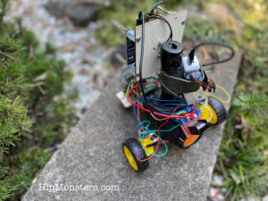
Originally, we set up this site to focus on woodcrafting and painting but as our interests grew, we have increasingly used Raspberry Pis to add motion and life into our work. This post will get you started using Raspberry Pi’s in your creations.

Please note, this material is provided for informational purposes only and is not a guide on how to create the designs. Please take a look at our disclaimer.

Why Raspberry Pi?

  1. Powerful computing platform with easy-to-use languages.
  2. Low energy consumption and runs quietly and cooly.
  3. Rich online support and user base.
  4. Has 26 pins built in enabling rapid integration with Internet of Things (IoT) technology.

RaspberryPi 5

Peripherals

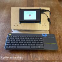
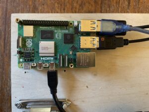
Today, most people developed on a laptop or tablet, but Raspberry Pi’s require old fashion peripherals: power cables, screen, keyboard and mouse. You need to setup a physical development environment and make sure you have all the necessary peripherals. Newer Raspberry Pi uses a Micro HDMI port so you will need a converter. We do a lot of coding on the couch so built a makeshift laptop as seen below.  

DIY RaspberryPi Laptop

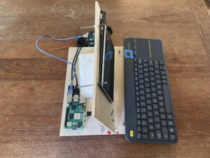
A side view of our Raspberry Pi laptop.

DIY RaspberryPi Laptop

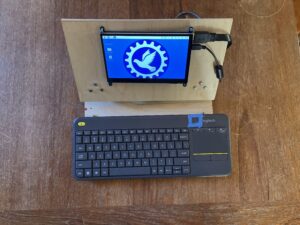
A front view of our laptop.

A mouse can get some to get use to so we recommend a wireless keyboard (seen above) with a built-in trackpad. One plus is the keyboard + trackpad only uses up one USB port.
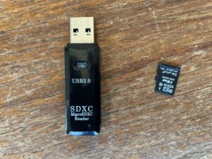
The Hard Drive

A Raspberry Pi’s OS is stored on a Micro SD. To start we recommend getting two with at least 64 GB. If you do any images or sound the drive fills up fast. You will also need at least two readers. One USB A for the Raspberry Pi when you transfer code and one for your other machine to build the OS image from.

SD card and reader

Building the OS Image

You can buy Micro SD cards with built in OS. If you do not have a laptop or desktop that is you only real option. You can also build your own OS image using tool provided by Raspberry Pi. You dan download it here: raspberrypi.com/software.

We recommend modifying the advance setting to pre-configure your login and Wi-Fi password.

Booting the Device

Make sure to use the appropriate power supply as specified by RaspBerryPi. Depending on the version, booting can take a while. Once it has completed booting you should see a screen that looks like most standard desktop environments.

Linux Desktop

Raspberry Pi’s OS is ARM version of Linux. If you have used Linux most of the standard tools will be available. If you have only used Windows or OSX the environment should seem very familiar. All the desktop environments follow the same basic principles. If you have never used a desktop environment this is a great place to start!

Configuring Your Environment

The keyboard defaults to UK. If you are not in the UK many of the keys will not work as expected. In Preferences, open up the Mouse and Keyboard Setting then click the Keyboard layout button at the bottom. In the combo box choose the appropriate country.

We also recommend a smaller or not image for the background to use less memory.

Developing Your Next Big Thing!

We started using Scratch as a development tool. If that works for you and makes sense keep using it! Here is a link on how to install it on a Raspberry PI.

We have migrated to mow using Python and C++. To write code we use the Geany Programmer’s Editor. It lacks some features of Visual Studio Code (what we develop on in Windows and OSX) but has a light foot print.

Typically, we write code for a Raspberry Pi on both a MacBook and the Raspberry Pi itself. We do find the MacBook is similar enough environment we do not need to change our code too much. If you look at our code in GitHub we you we often have different logic based on which environment the code is run on. Note: there are some packages that only work on Raspberry Pi such as interfaces to sensors. In these sections of the code, we have non-functioning stub if the platform is OSX.

We transfer code using the SD reader. Both OSX and Linux auto-detect SD cards when attacked but with Linux it can take a bit so be patient. Also, sometimes Linux cannot write to large SD card so try a small on first.

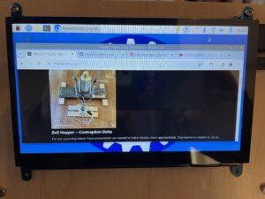
Our next post will dive deeper into the basic of programming Python on a Raspberry Pi. For now, if you have never used Linux or a desktop environment we recommend just browsing the Web using Chromium (the open source base to Chrome) to familiarize yourself.

Happy Creating!


Bell Hopper – Contraption Delta

For our upcoming Maker Faire presentation we wanted to make robotics more approachable. One barrier to robotics is, by its very nature, it lacks a human element. To bridge this robot-human divide, the bell hopper design requires two humans working together to power and control it. This only one goal, ring the bell.

Please note, this material is provided for informational purposes only and is not a guide on how to create the designs. Please take a look at our disclaimer.

Steampunk robot

The bell hopper ended up very similar to the first drawing of the concept, which is rare for us.  For the base board we used one of our small robot rig platforms. We use it to create supports for testing robot movements. It ended up looking so good we kept it for the final design. We always wanted ringing a bell to be the goal of the contraption, but originally did not think of using it as the head. Once we saw the bell with the body we changed the design to have it as the head because they fit so well together.

Steampunk robot

Here is a top view with the bell attached. The head’s weight caused a few engineering issues for us. The body was made of super light aluminum and the bell was heavy brass. To solve this we create a swinging counter balance inspired by the counter balance in Taipei 101.

air switch

For the switch to redirect the air we used a standard manual pneumatic lever. It is the same one we use for testing our robots.

Bike air pump

The power supply is a bicycle air pump painted bronze to look more steampunk.

Steampunk robot
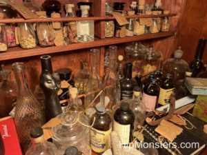
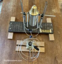
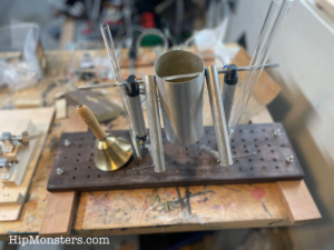
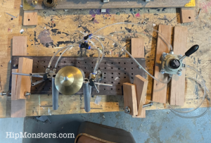
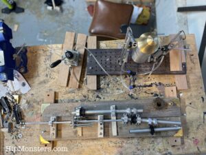
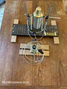
Here is the final design of the bell hopper.

It take two people working together to get the bells to ring. Cooperation is key! Come see it and more at this year’s Bay Area Maker Faire.

Happy Creating!


Leibniz Calculator- Contraption Gamma

For the upcoming Maker Faire the Hip Monster’s sisters team wanted a challenge. Something that required precision and also aligned well with our theme of education and steampunk artistry. What they choose to do was a true mechanical mind, a computer built with gears, the Leibniz Calculator.

Please note, this material is provided for informational purposes only and is not a guide on how to create the designs. Please take a look at our disclaimer.

DIY Leibniz Calculator

This proved to be our hardest project to date. While videos online had it look simple the precision proved difficult. We first designed a rig composed of separate segments of wood so we could explore different layouts for the gears and rods quickly. Arguable the most critical part, the step drum (the wheel like gear) was completed by the sister team in a few hours which gave us false hope the whole project would be easy.

DIY Leibniz calculator

The step drum shown above is in the center of the device. It was made from a circular piece of wood with nine evenly spaced holes along its edge. In each hole we put screws of different lengths that could be adjusted with bolts to “tune” the device on the fly. At first, we thought this would be a temporary solution but in the end we did not modify it. The device proved to be finicky and our step drum’s ability to be tuned was essential to get it to work.

DIY Leibniz Calculator

Over months of trial and error and rewatching youtube videos endlessly we finally had the Ah-Ha! moment. The rig stayed in the exact same position on our workbench as a parade of other projects were started then finished as it rested, in complete. Then everything just clicked, one sister released that we were thinking two dimensional when the problem was in the third dimension. The the other sister fixed the rig and then the Leibniz Calculator worked like a charm.

DIY Leibniz Calculator

Here is the final design with some added steampunk flourishes. See it in person at this year Bay Area Maker’s Faire. This project only succeed by everyone working together, listening to everyone’s ideas and refusing to get frustrated. In the end it feel more like a piece of art than calculator.

The above video shows the user adding. You use the Leibniz Calculator by first positioning the step drum to the value you want to add, subtract or multiply. Then you rotate the drum. As it spins it engages the counting gear which keeps track of the current value of the computation. The key is, since the step drums spokes are of different lengths when the drum is rotated the counting gear only is turned based on the length of the spokes. You add by rotating the drum clockwise, subtract by counter clockwise and multiply by doing a full rotating the number of time you want to multiply a value by.  For example, if you want to multiply 5 by 4 you set the step drum to 5 and rotate it 4 times.

DIY Leibniz calculator

Above you see the tens dial to the left, showing 2 which is twenty (5X4).


Happy Creating!

Number One On Its Own

Number One looks very simple, it’s just a burnt out hair drier with wheels. As out first design we opted for a wheeled robot that followed a more traditional form, but it has been repeatedly updated over the years and now is completely autonomous with a mind of its own, making it one of our most complex robots. Powered by a RaspberryPi, our new Number One is now a Edge AI mobile sensor.

Please note, this material is provided for informational purposes only and is not a guide on how to create the designs. Please take a look at our disclaimer.

DIY wheeled robot

The handle of the blow drier servers as a functional hub for the electronic component. The two batteries (one for the RaspberryPi and one for the motors) are attached to the back to allow for quick replacement. The camera is mounted at the top to provide a good overall view. The display, which is mostly for show, is forward facing. We added “bumpers” to the screen on each counter to help protect it in from falling or bumping in to something. The first screen hit a end table and developed a crack, which convinced us that it needed some armor.

DIY Wheeled Robot RaspberryPi

To protect the range finder, we added wooden bumper. Originally the range sensor had no protection, but after a few good hits we decided a bumper was a good idea. The range finder has proven to be sturdy but the wires to tend to fall off.

DIY Wheeled Robot RaspberryPi

Above is a back view. When we first built Number One it the components were completely attached using electrical tape. While this worked surprisingly well, it did not look good. Most components are now bolted on or attached using leather to help the robot look more aesthetic.

DIY Wheeled Robot RaspberryPi

The RaspberryPi is attached in front for easy access. The USB and other access ports are easily accessed allowing for quick repairs. We use a wireless keyboard to control the RaspberryPi. While the robot is autonomous (it makes decisions on its own) when it first gets power the AI part of the robot does not turn on. The robot can only become active after we execute a command. The original model turned on automatically, but that proved to be a bit of a headache when something went wrong.

Robot layout

The above image is the layout design using software from Fritzing.org. This is a far simpler layout that what we made for Number Two and Number Three. We may add more sensors over time, but to enable a fast response and to reduce power needs we decided to keep the number of sensors to a minimum.  Another difference is we are not using an Arduino to control the movement. For beginners this is a better design to learn with.

Here is Number One in action! Come see it live at this year’s Bay Area Maker Faire! 

You can download the code from our GitHub.

Happy Creating!