The HipMonster’s sister team decided to push our robotics to the next level. They were dissatisfied with remote controlled robots with no personality or pre-programmed robots who were predictable. What they wanted was a more independent android which could interact with and learn from its environment. While AI would drive this vision, just as important would be sensors and mechanics to enable the robots to come to life.
To start upgrading Number Two and Number Three, we explored different wiring layouts using Fritzing. Fritzing is an open source software program that lets you design and prototype component layouts virtually. This is a great tool for experts and beginners alike and can save you time and money in developing your next electronic project. The images below are exported from Fritzing and show layouts for our improved robots.
Please note, this material is provided for informational purposes only and is not a guide on how to create the designs. Please take a look at our disclaimer.
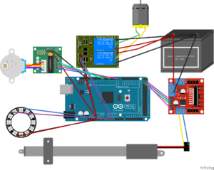
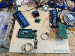
The above image is the layout for the Arduino and motors that allow the robots to move, as well as a decorative LED light. The linear actuators are controlled by H-Bridges and the motors by relays. We use a 12 volt battery for power. The Arduino receives commands from a RaspberryPi, which controls the LED light and brings everything together. Written in C++, the code for the Arduino is based off of our Walker code.
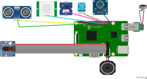
The above image is the layout for the RaspberryPi and the sensors. The signal processing and AI that is written in Python would live on the RaspberryPi. After much experimenting, we found it was best to have most sensors connected directly to the RaspberryPi and dedicate the Arduino completely to movement. Here is a good tutorial on using a motion sensor with a RaspberryPi.
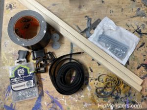
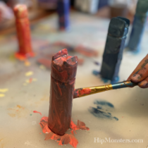
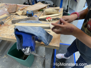
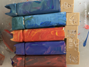
While we wanted a robot with modern AI and technology, we still wanted a steampunk feel. So we decided to use wood for the baseboard, use vintage wiring techniques, and use leather to secure components and wires.
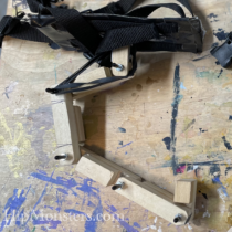
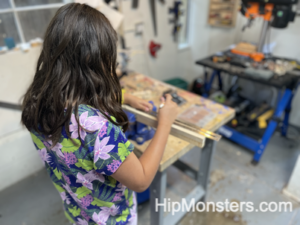
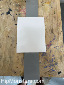
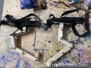
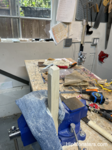
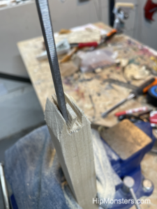
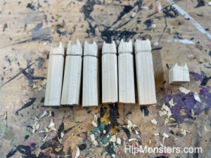
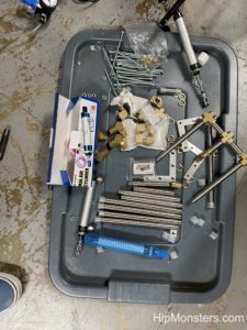
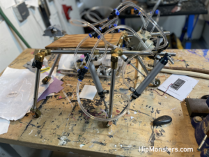
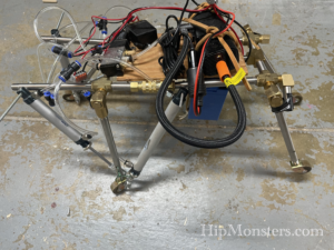
Once the layouts were finalized and the components acquired for our design, we started exploring different layouts for the baseboard. The baseboard is the most critical piece for our robot’s design. Not only does it secure all the electronics, but also provides structural support for the arm movements. While wiring the board, finding the right layout proved to be more of an art than science. The electronics, power, wiring and the robot’s skeleton all needed to fit together seamlessly, but often one or two components would refuse to play well with the others. The biggest issue was arranging the cabling to minimize stress on the connectors. For example, the HDMI slot needs to point downward or the stress would bend it over time. Number Two and Number Three also needed slightly different boards to work well with their different designs.
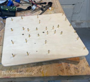
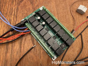
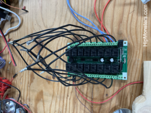
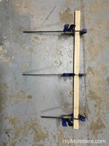
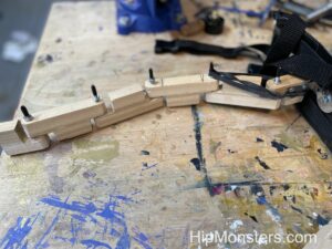
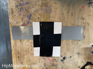
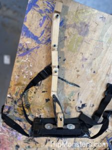
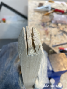
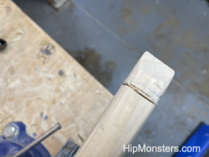
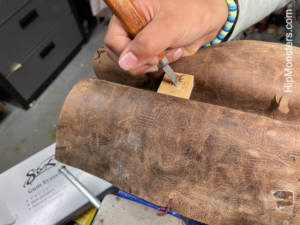
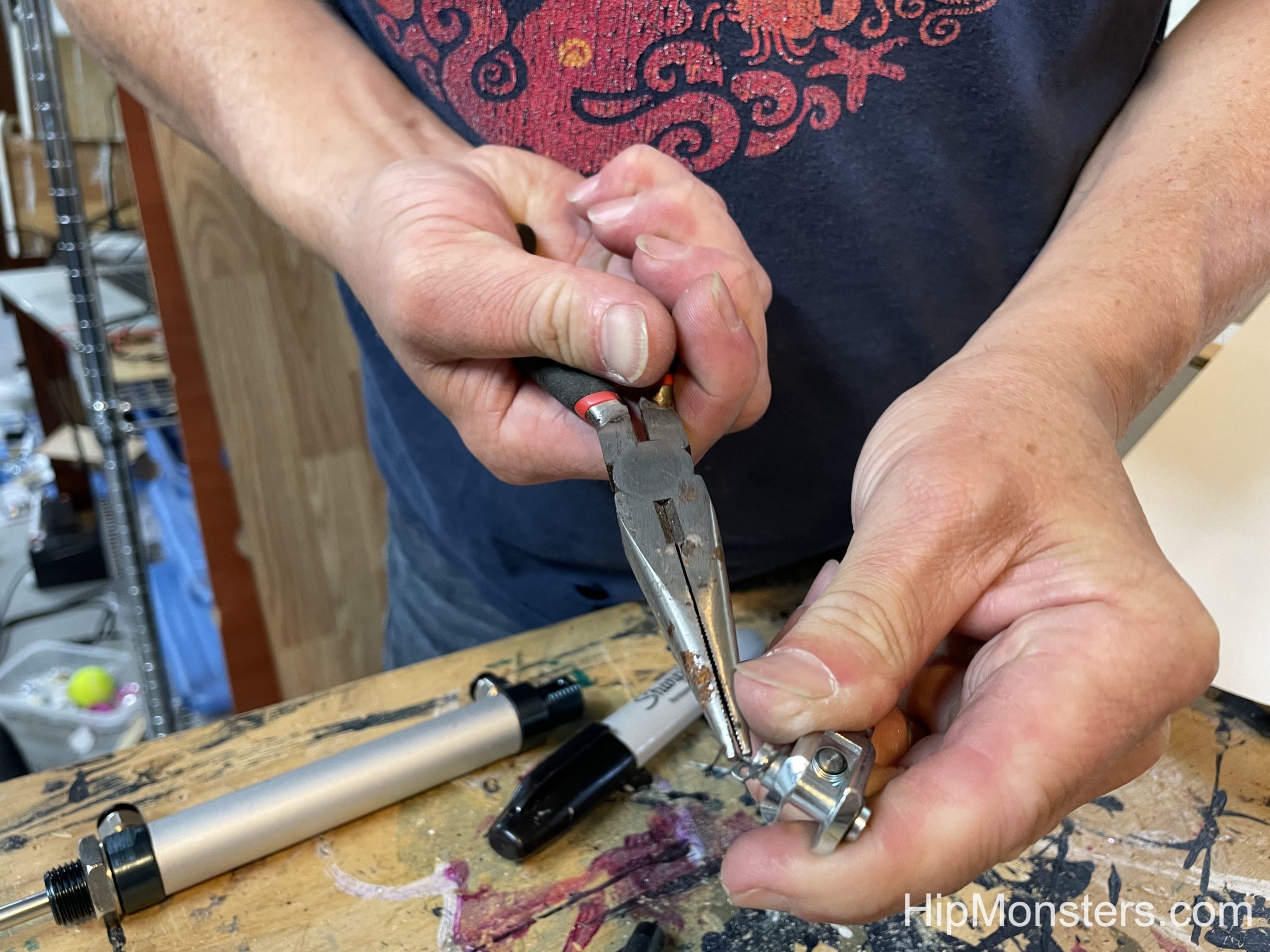
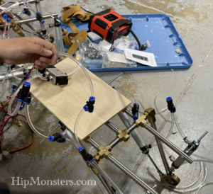
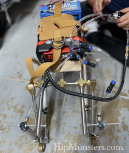
Above is the final form of the baseboard with the mounting screws attached. Remember to test the sizing on the mounting screws on each component before attaching them to the board. Also make sure to double check your measuring before drilling holes.
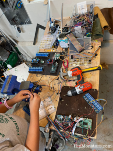
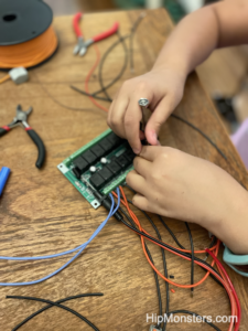
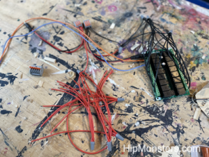
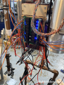
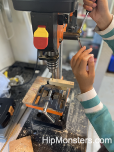
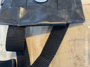
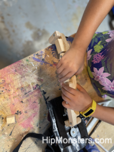
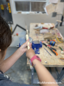
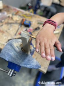
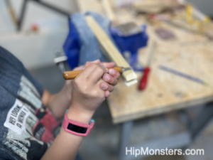
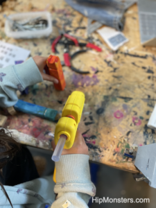
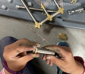
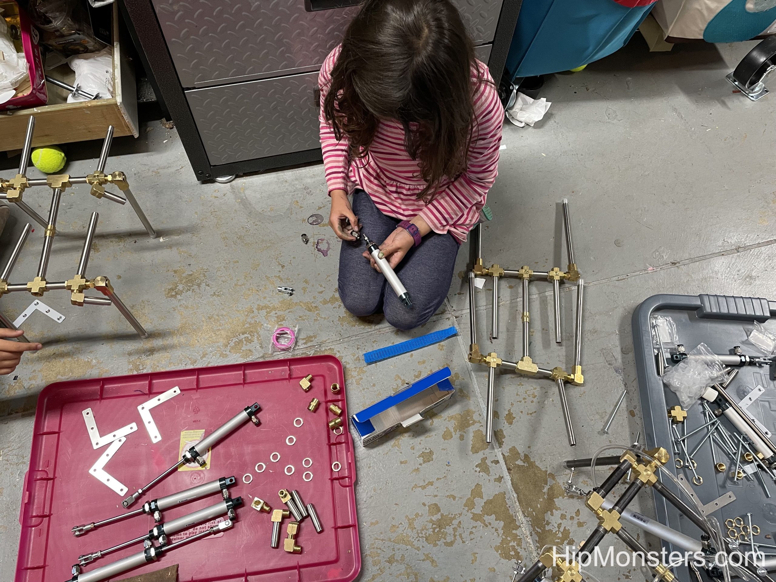
Here we are wiring the board for Number Two. We found it was good to test each connection after it was attached to make sure the wires had a clean connection and would not come off. While wiring two or three wires is easy, but after wiring a larger amount, mistakes can be made. If just one wire was in the wrong place or was stripped incorrectly, you could spend hours tracking it down. Thankfully both the Arduino and RaspberryPi are forgiving, but the sensors are not. If you wire a sensor incorrectly it will overheat and burn out.
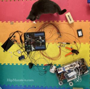
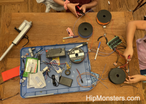
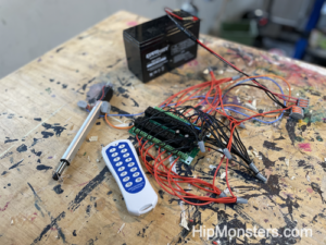
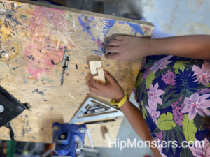
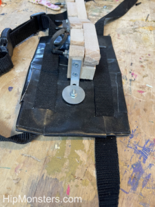
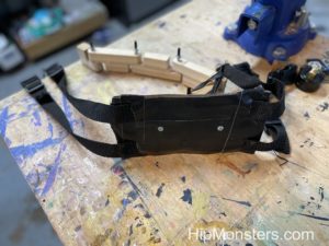
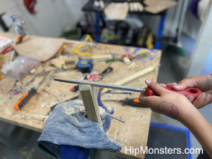
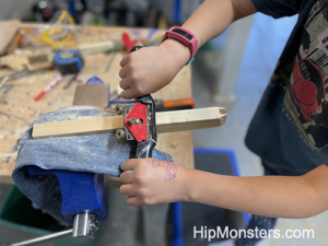
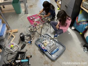
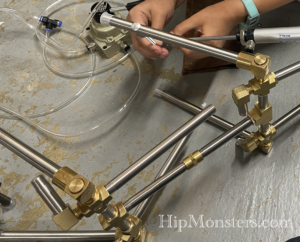
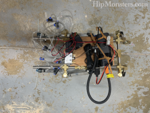
Here is another view of us wiring the board. Before attaching it to the robots, we tested everyone repeatedly. Even our cat helped in the testing by batting the wires as the motors kicked in.
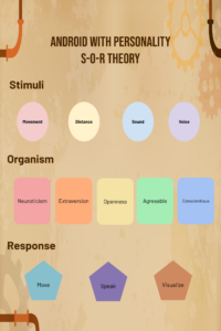
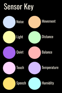
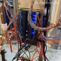
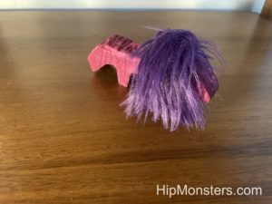
And here is the Number Three with its new board in action! The color circle indicates which sensor is receiving input. When the robot receives stimuli, it responds by either moving or speaking to try and encourage more stimuli.
Come see Number Three, Number Two, and more at this year’s Bay Area Maker Faire.
Happy Creating!


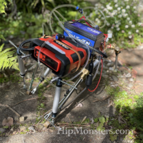


 Here is Number Six walking in our yard.